Eureka AIR delivers breakthrough ideas for toughest innovation challenges, trusted by R&D personnel around the world.

Servo pattern based tape tension control for tape drives

a technology of tension control and tape drive, applied in the direction of mechanical tension control of carrier, maintaining head carrier alignment, instruments, etc., can solve the problems of low readback signal amplitude, poor data transfer reliability, damaged media and therefore data loss

Inactive Publication Date: 2005-08-23
INTELLECTUAL DISCOVERY INC
View PDF20 Cites 12 Cited by
  • Summary
  • Abstract
  • Description
  • Claims
  • Application Information

AI Technical Summary

Benefits of technology

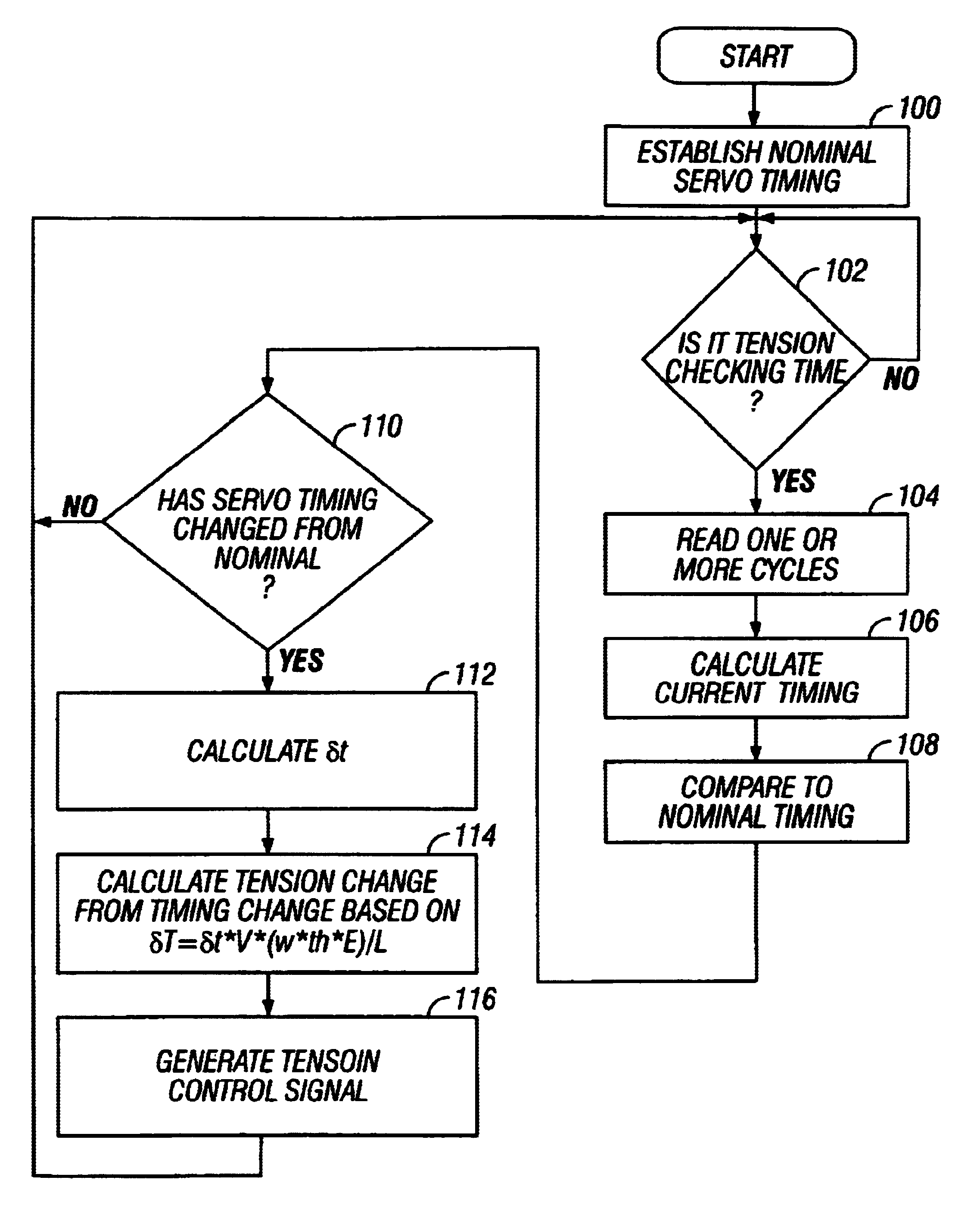
[0017]FIG. 6 is a block diagram showing an exemplary embodiment of a tape tension contro

Problems solved by technology

Improper tape tension can lead to unreliable positioning of the tape relative to the read / write head(s), which can produce low readback signal amplitude and poor data transfer reliability, and causes poor stacking on the reels which can result in damaged media and therefore data loss.
These options can be insufficient in providing precise tension control and may require additional hardware in the tape path that can negatively contribute to high performance tape path requirements.
These options are also undesirable because they require added hardware or additional write / read sequences for their implementation.

Method used


Image

  • Servo pattern based tape tension control for tape drives
  • Servo pattern based tape tension control for tape drives
  • Servo pattern based tape tension control for tape drives

Examples


Embodiment Construction

[0019]The invention will now be described by way of exemplary embodiments shown by the drawing figures (which are not necessarily to scale), in which like reference numerals indicate like elements in all of the several views.

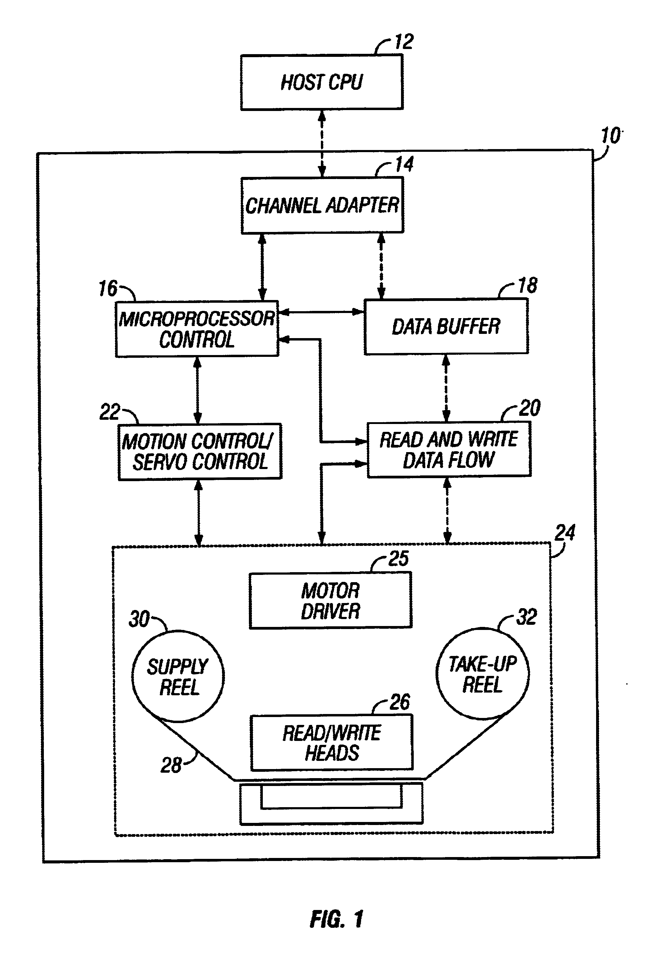
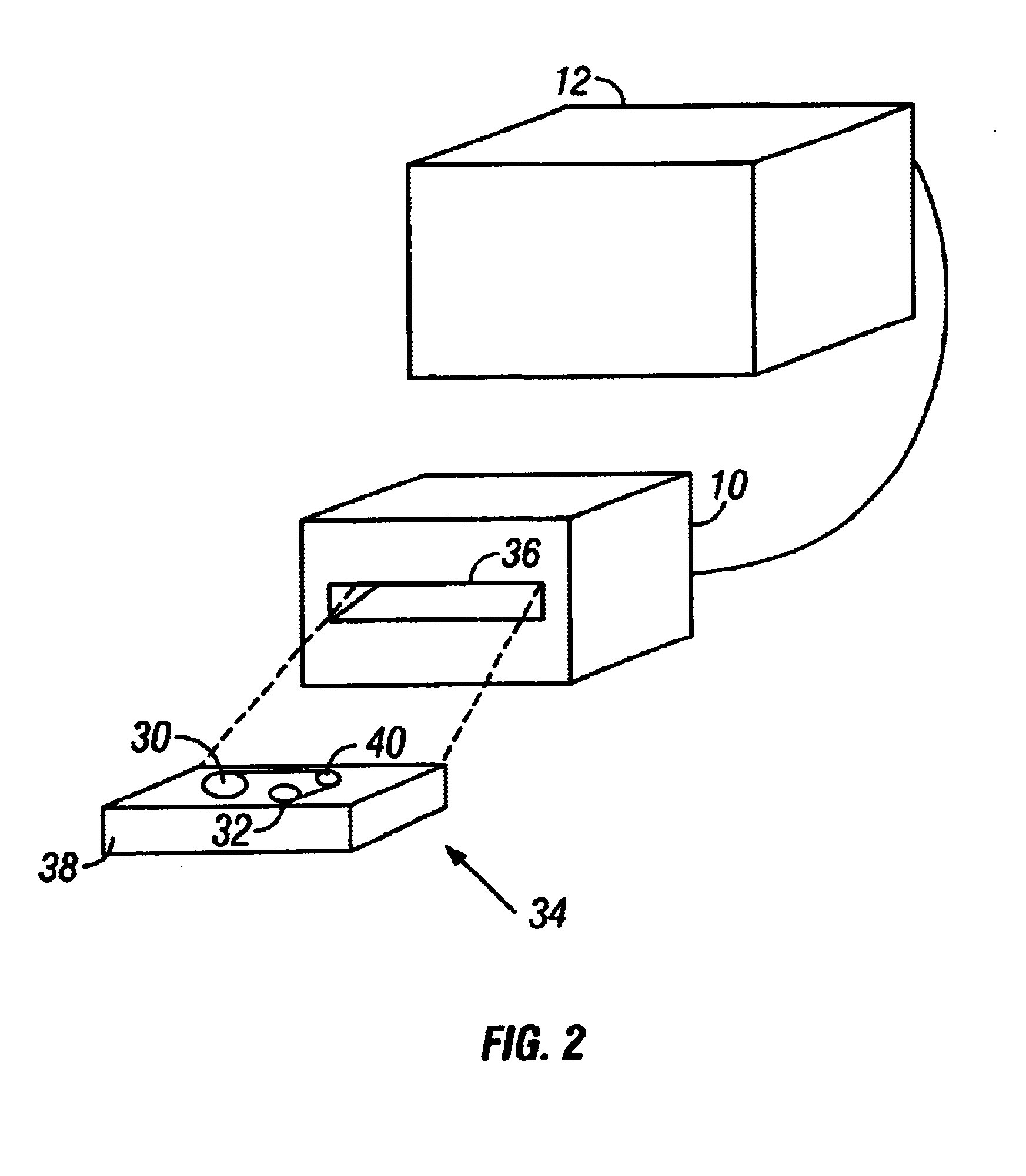
[0020]Turning to FIG. 1, the inventive concepts herein described may be embodied in a tape drive data storage device (tape drive) 10 for storing and retrieving data by a host digital processing device 12, which could be a general purpose computer of other processing apparatus adapted for data exchange with the tape drive 10. The tape drive 10 includes plural components providing a control and data transfer system for reading and writing host data on a magnetic tape medium. Those components include a channel adapter 14, a microprocessor controller 16, a data buffer 18, a read / write data flow circuit 20, a motion control system 22, and a tape interface system 24 that includes a motor driver circuit 25.

[0021]The microprocessor controller 16 provides overhead contro...


PUM


Abstract

A system and method of controlling tape tension during operation of a tape drive by making use of pre-existing timing based servo patterns formatted on the media. Changes in servo pattern timing are read at regular intervals and used to calculate changes in tension, with the torque of the tape reel motors being adjusted accordingly.

Description

BACKGROUND OF THE INVENTION[0001]1. Field of the Invention[0002]This invention relates to tape drive data storage systems. More particularly, the invention is directed to the control of tape tension during tape drive operation to facilitate data read / write accuracy.[0003]2. Description of the Prior Art[0004]By way of background, during operation in a tape drive data storage apparatus, a tape medium is transferred from a supply reel to a take-up reel while data is read from or written to tape by one or more read / write heads. Typically, the tape medium and the supply and take-up reels are mounted inside a tape cartridge that is inserted into a slot in the tape drive so that the tape is in magnetic contact with the read / write heads. The tape is advanced past the read / write head(s) by means of a pair of motors, one for each reel, which drive the reels at a desired tape speed. The motor that drives the supply reel is sometimes called the trailing motor and the motor that drives the take-...

Claims


Application Information

Patent Timeline
IPC IPC(8): G11B15/43G11B15/46G11B15/52G11B5/584
CPCG11B5/584G11B15/43G11B15/52
Inventor HARPER, DAVID H.TAYLOR, MARK A.
Owner INTELLECTUAL DISCOVERY INC
Why Eureka
Eureka Blog
Learn More