Adaptive EEPROM storage system for tire pressure loss detection

a technology of tire pressure loss and storage system, which is applied in the direction of pressure difference measurement between multiple valves, instruments, digital computer details, etc., can solve the problems of limited road adhesion, tire pressure loss can have an extremely devastating effect, and the vehicle is no longer controllable, so as to eliminate spikes or brief disturbances

Active Publication Date: 2005-08-23
ROBERT BOSCH GMBH
View PDF18 Cites 8 Cited by
  • Summary
  • Abstract
  • Description
  • Claims
  • Application Information

AI Technical Summary

Benefits of technology

[0009]In an example embodiment, provision is made for selecting the vehicle speed, as a differentiation criterion between the individual monitoring modes, as the driving state variable. This makes possible a monitoring process adapted to the instantaneous driving state.
[0010]In accordance with the present invention, provision is made for equipping each monitoring mode with at least one calibration mode. Provision is further made for each calibration mode to contain at least one calibration variable. It is thus possible to achieve, within the individual monitoring modes, fine gradations that permit accurate identification and monitoring of the operating state of the tire. In order to adapt the determination of the calibration variables as closely as possible to the actual operation of the vehicle, the calibration variables are determined as a function of a series of parameters. At least one tire state variable, one driving state variable, one calibration request, and / or the monitoring mode, for example, are included in the determination of the calibration variable. It is thus possible to eliminate spikes or brief disturbances from the determination by taking an average of several tire state variables in the determination of the calibration variables.

Problems solved by technology

A sudden pressure decrease, which regularly occurs as an indication of tire damage, can result in limited road adhesion and, in some cases, can render the vehicle no longer controllable.
At high speeds, in particular, tire pressure losses can therefore have an extremely devastating effect.

Method used


Image

  • Adaptive EEPROM storage system for tire pressure loss detection
  • Adaptive EEPROM storage system for tire pressure loss detection
  • Adaptive EEPROM storage system for tire pressure loss detection

Examples


Embodiment Construction

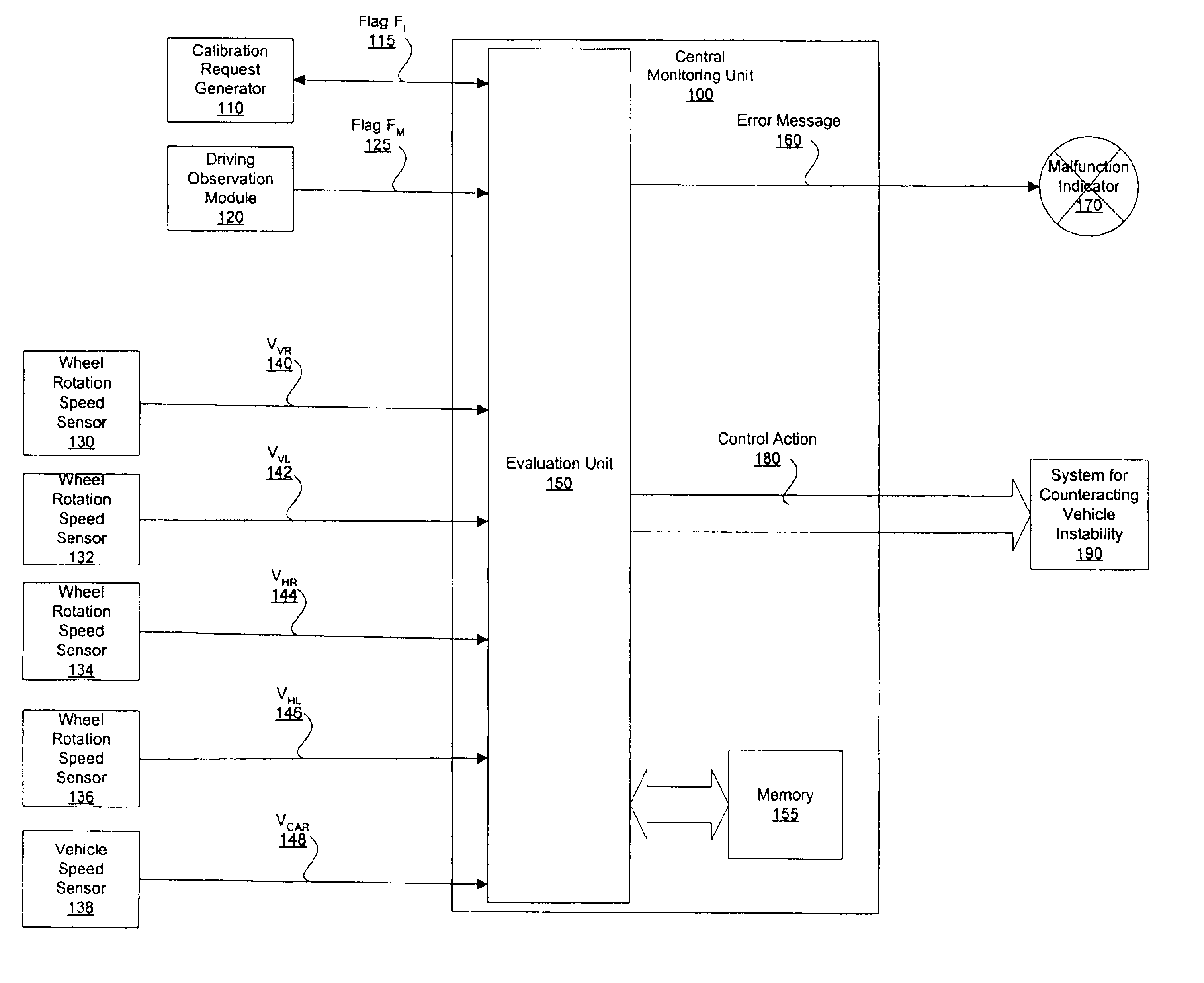
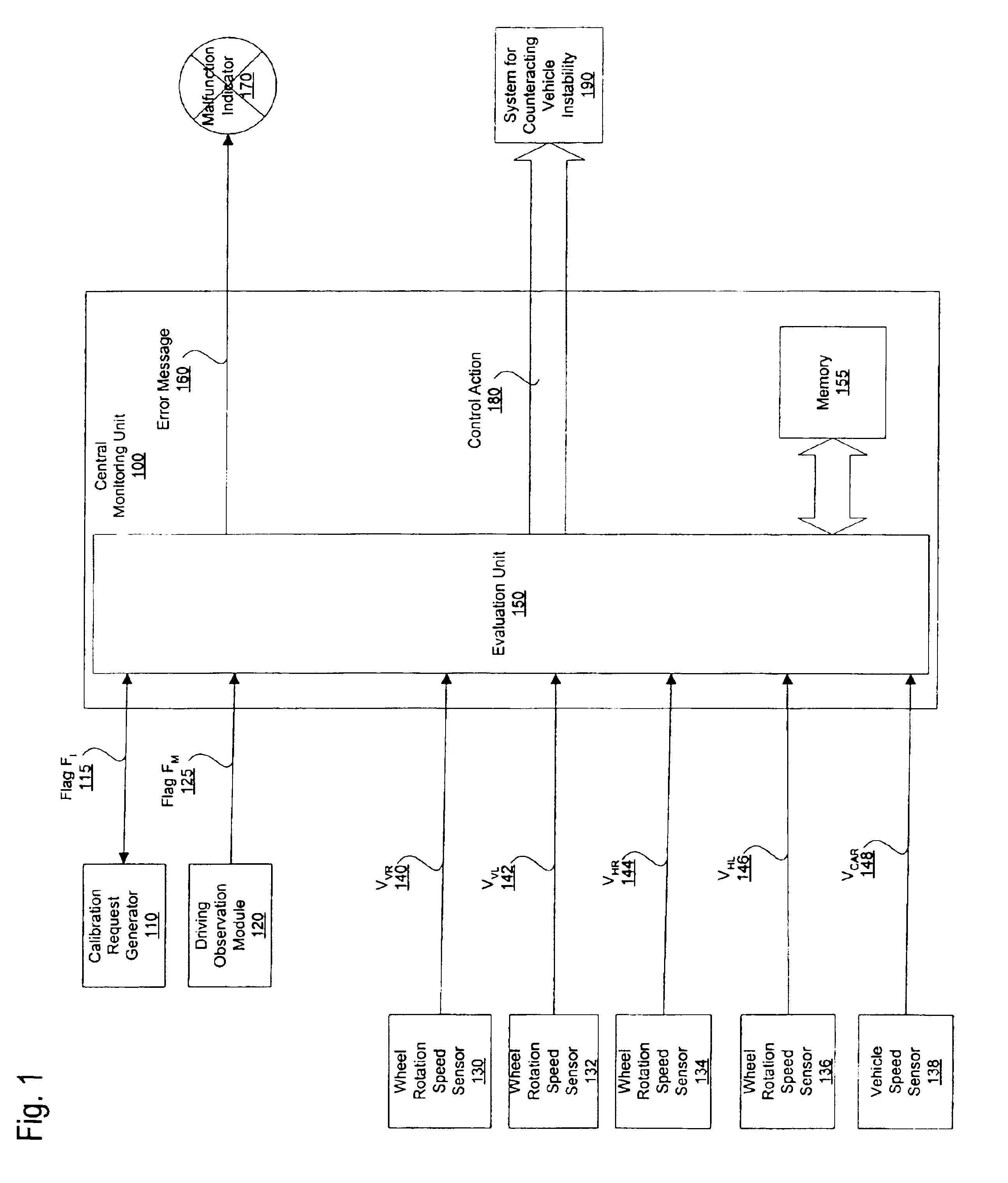
[0024]FIG. 1 shows an exemplary embodiment for monitoring of a vehicle having four tires. An adaptation of the example to a vehicle having additional tires is certainly possible, but not necessary for presentation of the example. For acquisition of the monitoring parameters necessary for monitoring, each wheel equipped with a tire possesses a wheel rotation speed sensor (130 through 136) for ascertaining the wheel rotation speed. From these wheel rotation speed sensors (130 through 136), the wheel rotation speed variables vVR (140), vVL (142), vHR (144), and vHL (146), which represent the wheel rotation speeds, are forwarded to central monitoring unit 100. To complete the driving-dynamics variables for monitoring, monitoring unit 100 reads out of a corresponding system 138 a variable vcar (148) representing the vehicle speed. In block 150, tire state variables ΔvA, ΔVD which represent the tire state of the wheels are ascertained from these read-in values.

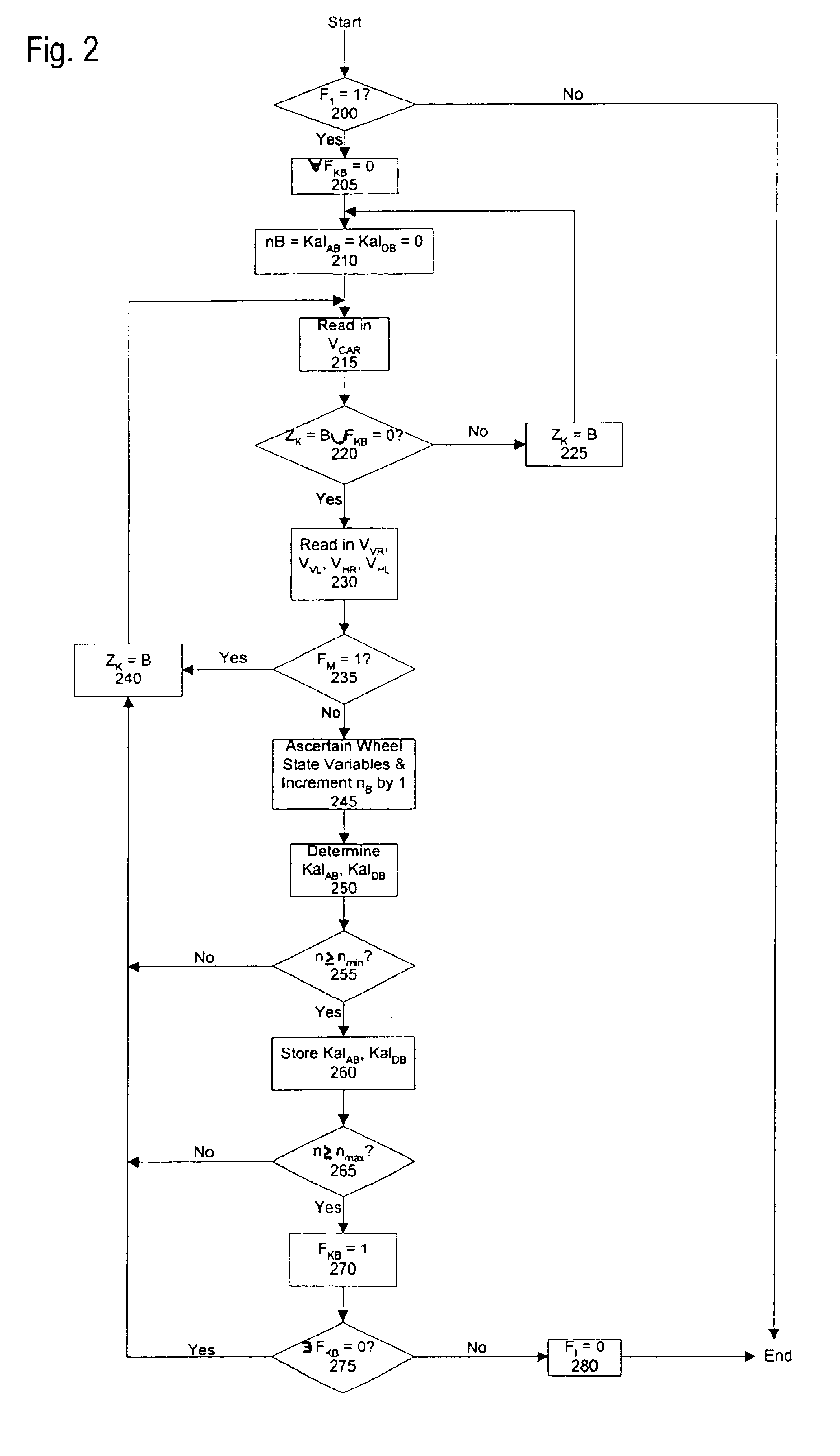
[0025]An initialization, whi...


PUM

PropertyMeasurementUnit
speedaaaaaaaaaa
timeaaaaaaaaaa
wheel rotation speedsaaaaaaaaaa

Abstract

A method and an apparatus for monitoring an operating state of at least one tire of a vehicle are provided. The monitored operating state may be, for example, the air pressure of the tire. One tire state variable that represents the current operating state of the tire, and one calibration variable that represents the target tire state of the tire, are taken into consideration in the monitoring. The monitoring is accomplished in different monitoring modes, i.e., the particular monitoring mode employed is determined as a function of at least one driving state variable representing the driving state. In an example embodiment, for a given driving state variable, the vehicle speed is selected as the differentiation criterion for the different monitoring modes.

Description

FIELD OF THE INVENTION[0001]The present invention relates to a method and an apparatus for monitoring an operating state of at least one tire of a vehicle.BACKGROUND INFORMATION[0002]The tires of a vehicle are among the systems most critical to driving safety during operation of the vehicle. A sudden pressure decrease, which regularly occurs as an indication of tire damage, can result in limited road adhesion and, in some cases, can render the vehicle no longer controllable. At high speeds, in particular, tire pressure losses can therefore have an extremely devastating effect. Prompt detection of a defective tire can thus make a considerable contribution to driving safety.[0003]Systems which monitor the state of a tire, in particular the air pressure, are known in the art. In addition to direct determination of the air pressure of a tire, the rotation speeds of the wheels can be employed in order to determine a change in tire pressure. For example, changes in the rotation speeds of ...

Claims


Application Information

Patent Timeline
Patent Type & Authority Patents(United States)
IPC IPC(8): B60C23/06G01L17/00B60C23/02
CPCB60C23/061
Inventor POLZIN, NORBERT
Owner ROBERT BOSCH GMBH
Why Eureka
Try Eureka