Service station leak detection and recovery system

a technology for recovery systems and service stations, applied in fluid tightness measurement, instruments, liquid transfer devices, etc., can solve problems such as serious concern, sensor failure or and failure of outer piping

Inactive Publication Date: 2005-08-30
GILBARCO
View PDF78 Cites 32 Cited by
  • Summary
  • Abstract
  • Description
  • Claims
  • Application Information

AI Technical Summary

Benefits of technology

[0008]While the parent application of the present invention capitalizes on the synergies created between the tank monitoring equipment, the submersible turbine pump (STP), and the fuel dispenser in a fueling environment, the present application supplements this disclosure by offering an alternative leaked fuel collection point. However, for continuity, the original, underlying invention is discussed first. A fluid connection that carries a fuel supply for eventual delivery to a vehicle is made between the underground storage tank and the fuel dispensers via double-walled piping. Rather than use the conventional sumps and low point drains, the present invention drains any fuel that has leaked from the main conduit of the double-walled piping back to the underground storage tank. This addresses the need to recapture the fuel for reuse and to reduce fuel that is stored in sumps which must later be retrieved and excavated by costly service personnel.
[0009]The fluid in the outer conduit may drain to the underground storage tank by gravity coupled with the appropriately sloping piping arrangements, or a vacuum may be applied to the outer conduit from the vacuum in the underground storage tank. The vacuum will drain the outer conduit. Further, the return path may be fluidly isolated from the sumps, thus protecting the fuel from contamination.
[0011]The daisy chain arrangement allows for leak detection probes to be placed within each fuel dispenser so that leaks between the fuel dispensers may be detected. The multiplicity of probes causes leak detection redundancy and helps pinpoint where the leak is occurring. Further, the multiple probes help detect fuel leaks in the outer conduit of the double-walled piping. This is accomplished by verifying that fuel dispensers downstream of a detected leak also detect a leak. If they do not, a sensor has failed or the outer conduit has failed. A failure in the outer piping is cause for serious concern as fuel may be escaping to the environment and a corresponding alarm may be generated.
[0012]Another possibility with the present invention is to isolate sumps, if still present within the fuel dispenser, from this return path of captured leaking fuel such that contaminants are precluded from entering the leaked fuel before being returned to the underground storage tank. In this manner, fuel may potentially be reused since it is not contaminated by other contaminants, such as water, and reclamation efforts are easier. Since the fuel is returned to the underground storage tank, there is less danger that a sump overflows and allows the fuel to escape into the environment.

Problems solved by technology

If they do not, a sensor has failed or the outer conduit has failed.
A failure in the outer piping is cause for serious concern as fuel may be escaping to the environment and a corresponding alarm may be generated.

Method used


Image

  • Service station leak detection and recovery system
  • Service station leak detection and recovery system
  • Service station leak detection and recovery system

Examples


first embodiment

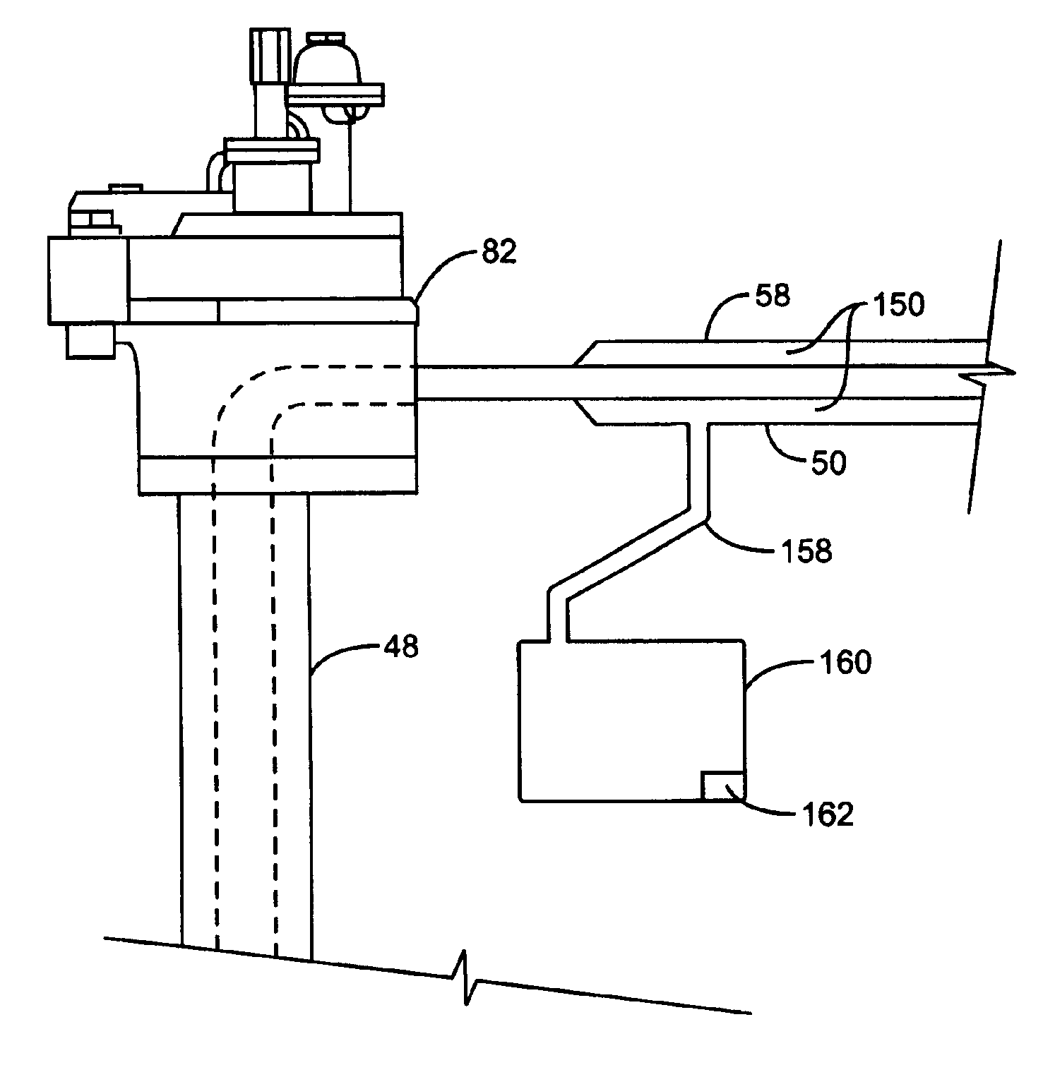
[0041]the connection to the daisy chaining double-walled pipe 50 to the underground storage tank 34 is illustrated in FIG. 5. The daisy chaining double-walled pipe 50 connects to a distribution head 82, which in turn connects to the double-walled pipe 48. Portions of the submersible turbine pump, such as the pump and the motor, may be contained within the distribution head 82. The boom 84 of the submersible turbine pump is positioned within the underground storage tank 34, preferably below the level of fuel 86 within the underground storage tank 34. For a more complete exploration of the submersible turbine pump, reference is made to U.S. Pat. No. 6,223,765 assigned to Marley Pump Company, which is incorporated by reference in its entirety, and the product exemplifying the teachings of the patent explained in Quantum Submersible Pump Manual: Installation and Operation, also produced by the Marley Pump Company, also incorporated by reference in its entirety. In this embodiment, fuel ...

second embodiment

[0042]the connection of the daisy chaining double-walled pipe 50 to the underground storage tank 34 is illustrated in FIG. 6. The distribution head 82 is substantially identical to the previously incorporated U.S. Pat. No. 6,223,765. The daisy chaining double-walled pipe 50, however, comprises a fluid connection 88 to the double-walled pipe 48. This allows the fuel in the outer wall 58 to drain directly to the underground storage tank 34, instead of having to provide a return path through the distribution head 82. Further, the continuous fluid connection from the underground storage tank 34 to the outer wall 58 causes any vacuum present in the underground storage tank 34 to also be existent in the outer wall 58 of the daisy chaining double-walled pipe 50. This vacuum may help drain the fuel back to the underground storage tank 34. In an exemplary embodiment, the fluid connection 88 may also be double-walled so as to comply with any appropriate regulations.

[0043]FIG. 7 illustrates th...


PUM


Abstract

A fueling environment distributes fuel from a fuel supply to fuel dispensers in a daisy chain arrangement with a double-walled piping system. Fuel leaks that occur within the double-walled piping system are returned to the underground storage tank or a sump proximate the submersible turbine pump by the outer wall of the double-walled piping. This preserves the fuel for later use and helps reduce the risk of environmental contamination. Leak detectors may also be positioned in to fuel dispensers detect leaks and provide alarms for the operator, and help pinpoint leak detection that has occurred in the piping system proximate to a particular fuel dispenser or in between two consecutive fuel dispensers.

Description

RELATED APPLICATIONS[0001]The present application is a divisional of U.S. patent application Ser. No. 10 / 288,245, filed Nov. 5, 2002, pending, which is a continuation-in-part of U.S. patent application Ser. No. 10 / 173,990, filed Jun. 18, 2002, which is herein incorporated by reference in its entirety.FIELD OF THE INVENTION[0002]The present invention relates to a fuel recovery system for recovering leaks that occur in fuel supply piping in a retail fueling environment.BACKGROUND OF THE INVENTION[0003]Managing fuel leaks in fueling environments has become more and more important in recent years as both state and federal agencies impose strict regulations requiring fueling systems to be monitored for leaks. Initially, the regulations required double-walled tanks for storing fuel accompanied by leak detection for the tanks. Subsequently, the regulatory agencies have become concerned with the piping between the underground storage tank and the fuel dispensers and are requiring double-wal...

Claims


Application Information

Patent Timeline
Patent Type & Authority Patents(United States)
IPC IPC(8): B67D5/60B67D5/32B67D7/32B67D7/78
CPCB67D7/3209B67D7/78Y10T137/5762B67D2007/746
Inventor HUTCHINSON, RAY J.
Owner GILBARCO
Why Eureka
Try Eureka