Device for measuring the angle and/or the angular velocity of a rotatable body and/or the torque acting upon said body

a technology of angular velocity and rotatable body, which is applied in the direction of instruments, apparatus for force/torque/work measurement, and fluid detection at leakage point, etc., can solve the problems of laborious evaluation using an arc tangent method, large safety requirements, and inability to integrate, so as to increase the measuring accuracy and/or the measuring range of the devi

Inactive Publication Date: 2005-08-30
ROBERT BOSCH GMBH
View PDF10 Cites 45 Cited by
  • Summary
  • Abstract
  • Description
  • Claims
  • Application Information

AI Technical Summary

Benefits of technology

[0027]The markings of the two devices are preferably selected so that the classical or modified vernier method can be applied anew to the respective measured results. This increases the measuring accuracy and/or the measuring range ...

Problems solved by technology

A specific application of such a device is a steering-wheel angle sensor, whereby enormous safety requirements exist.
This device therefore offers the advantage that multiple rotations can be detected, but it is disadvantageous in that the detection takes place by means of the interconnection of toothed wheels and therefore not in a contactless manner.
Moreover, the installation space required for such a device is relatively large, making it difficult to integrate it, particularly on the...

Method used


Image

  • Device for measuring the angle and/or the angular velocity of a rotatable body and/or the torque acting upon said body
  • Device for measuring the angle and/or the angular velocity of a rotatable body and/or the torque acting upon said body
  • Device for measuring the angle and/or the angular velocity of a rotatable body and/or the torque acting upon said body

Examples


Embodiment Construction

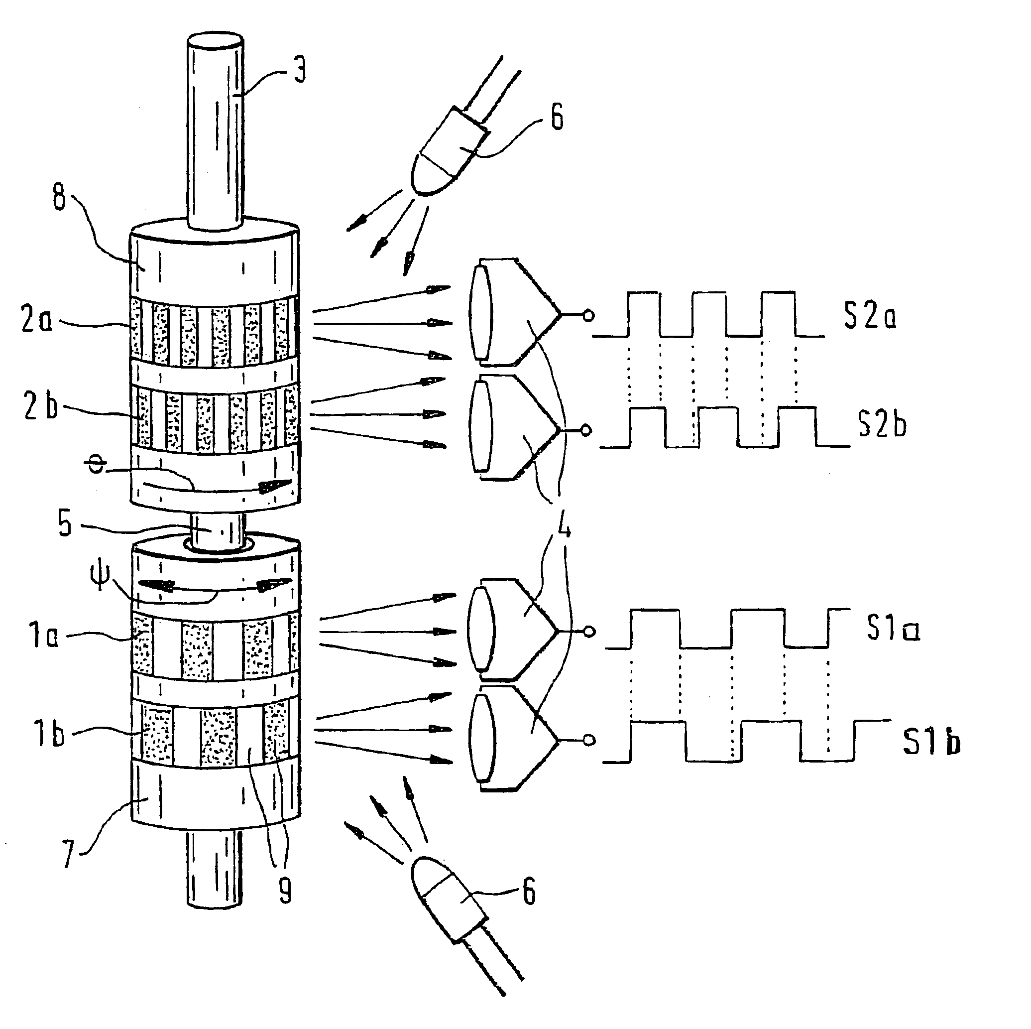
[0043]In the following description, reference is largely made exclusively to magnetic fields and, in the case of the exemplary embodiment shown in FIG. 4, reference is made to an electrical field; one skilled in the art should recognize, however, that random combinations, i.e., any electromagnetic fields, can be used. For example, light diodes could be used as field poles instead of magnets, the emitted field of which can be detected using appropriate opto-electronic sensors.

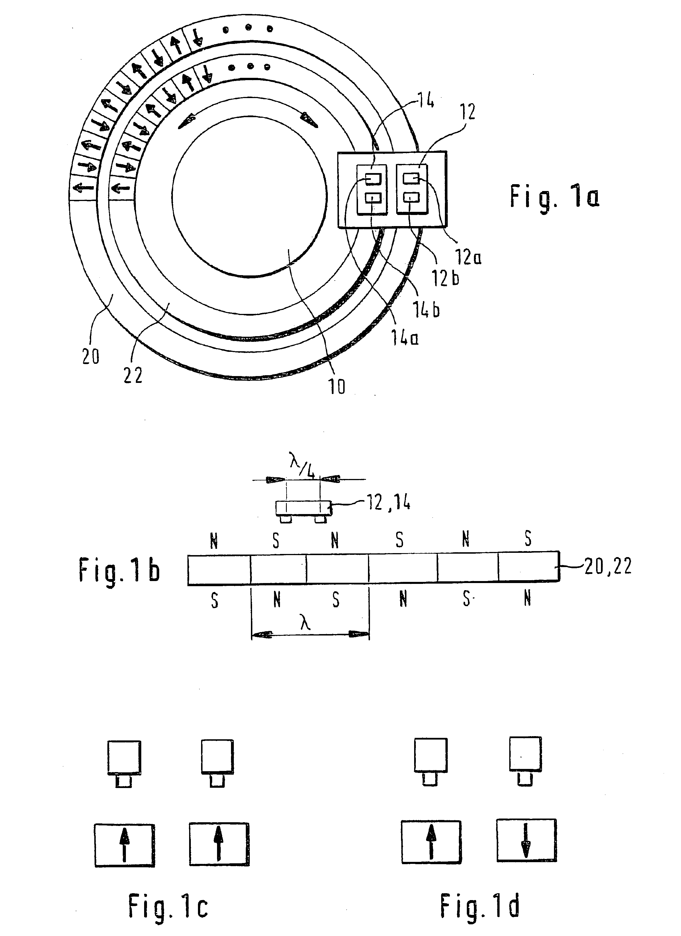
[0044]The exemplary embodiment shown in FIG. 1 includes a disk mounted on the steering axle 10, on which disk code tracks 20, 22 are provided. Each of the code tracks 20, 22 comprises a plurality of alternatingly arranged permanent magnets, as indicated by the arrows pointing in different directions. The two code tracks 20, 22 are distributed differently, whereby it is particularly advantageous for the smallest possible difference to exist, e.g., a difference of only one pole pair. In the exemplary embodiment sh...


PUM


Abstract

A device for measuring an angle and/or the torque acting on a rotatable body is proposed according to the invention, whereby the rotational angle is detected by means of magnetic or optical sensors. In particular, in a preferred exemplary embodiment, two devices (7, 8) are proposed, each of which comprises two optically readable code tracks. The two code tracks (1a, 1b or 2a, 2b) on one device (7 or 8) are similar in design and are offset in relation to each other, so that associated sensors (4) output a digital signal. The rotational angle is calculated based on the lag between the two digital signals. In a further embodiment it is provided that a torsion element (5) having a known torsional stiffness is situated between the two devices (7, 8). Torque transferred by the rotatable body (3) can also be calculated therefore from the angular difference of the two devices 7, 8. The device is used preferably in the steering axle of a motor vehicle.

Description

BACKGROUND OF THE INVENTION[0001]The invention concerns in general a device for measuring the angle and / or angular velocity of a rotatable body, and, in particular, a device for measuring the angle and / or angular velocity of a rotatable body and / or of the torque acting on it.[0002]A very exact determination of a rotational angle is necessary for many systems, e.g., in the automotive industry. A specific application of such a device is a steering-wheel angle sensor, whereby enormous safety requirements exist.[0003]A device is made known in DE-A-195 06 938 belonging to the applicant, which said device is used to measure the angle and / or the angular velocity of the rotatable body, in particular a body that can be rotated by more than 360°, according to the preamble of claim 1. In the case of the known device, the first and second devices are each formed out of a toothed wheel with associated angle sensor, whereby the two toothed wheels—when the numbers of teeth are different—are in mes...

Claims


Application Information

Patent Timeline
IPC IPC(8): B62D15/02B62D15/00G01L5/22G01L3/12G01P3/487G01M3/12G01P3/42G01D5/245G01D5/12G01P3/486B62D5/04B62D5/06G01B11/26G01D5/30
CPCB62D6/10B62D15/0215G01D5/2451G01L3/12G01L5/221G01M3/12G01P3/486G01P3/487B60G2204/11
Inventor HEISENBERG, DAVIDKLOTZBUECHER, THOMASHAAS, GUNTERDORFMUELLER, LUTZSIEGLE, HENRIKWENZLER, AXELMARX, KLAUSJOST, FRANZNOLTEMEYER, RALFFREITAG, MARTIN
Owner ROBERT BOSCH GMBH
Why Eureka
Try Eureka