Steam turbine packing spring

a technology of steam turbines and packing springs, which is applied in the direction of shock absorbers, machines/engines, transportation and packaging, etc., can solve the problems of high cycle fatigue of packing rings and/or springs, interfere with other hardware, and each has significant disadvantages, so as to reduce stress, reduce the risk of high cycle fatigue or improper sealing operation, the effect of increasing product li

Inactive Publication Date: 2005-08-30
GENERAL ELECTRIC CO
View PDF15 Cites 13 Cited by
  • Summary
  • Abstract
  • Description
  • Claims
  • Application Information

AI Technical Summary

Benefits of technology

[0007]This invention provides additional space in the existing or new seal location. This space can be used to include additional devices or added material for reducing stress and increasing product life. The invention also provides a seal support that prevents pivoting about the support point, thus reducing the risk of high cycle fatigue or improper seal operation, and also permits a spring rate that may vary throughout the stroke of the seal.

Problems solved by technology

While numerous spring designs have been used over the years, each has significant disadvantages.
Another disadvantage is the fact that each packing ring segment is contacted in only one location, i.e., at the mid point of the seal segment.
If a cyclic force were applied to the packing ring, it would be possible to create a vibratory mode which could lead to high cycle fatigue of the packing ring and / or spring.
However, the coil spring design requires multiple cylindrical pockets milled into the back of each seal segment.
These milled pockets may interfere with other hardware that may be installed into the segment.
In addition, variable spring rates are not easy to attain without nesting multiple coil springs.
It may be desirable to control the spring rate, but that may unload one of the nested springs, allowing it to vibrate and become damaged.

Method used


Image

  • Steam turbine packing spring
  • Steam turbine packing spring
  • Steam turbine packing spring

Examples


Embodiment Construction

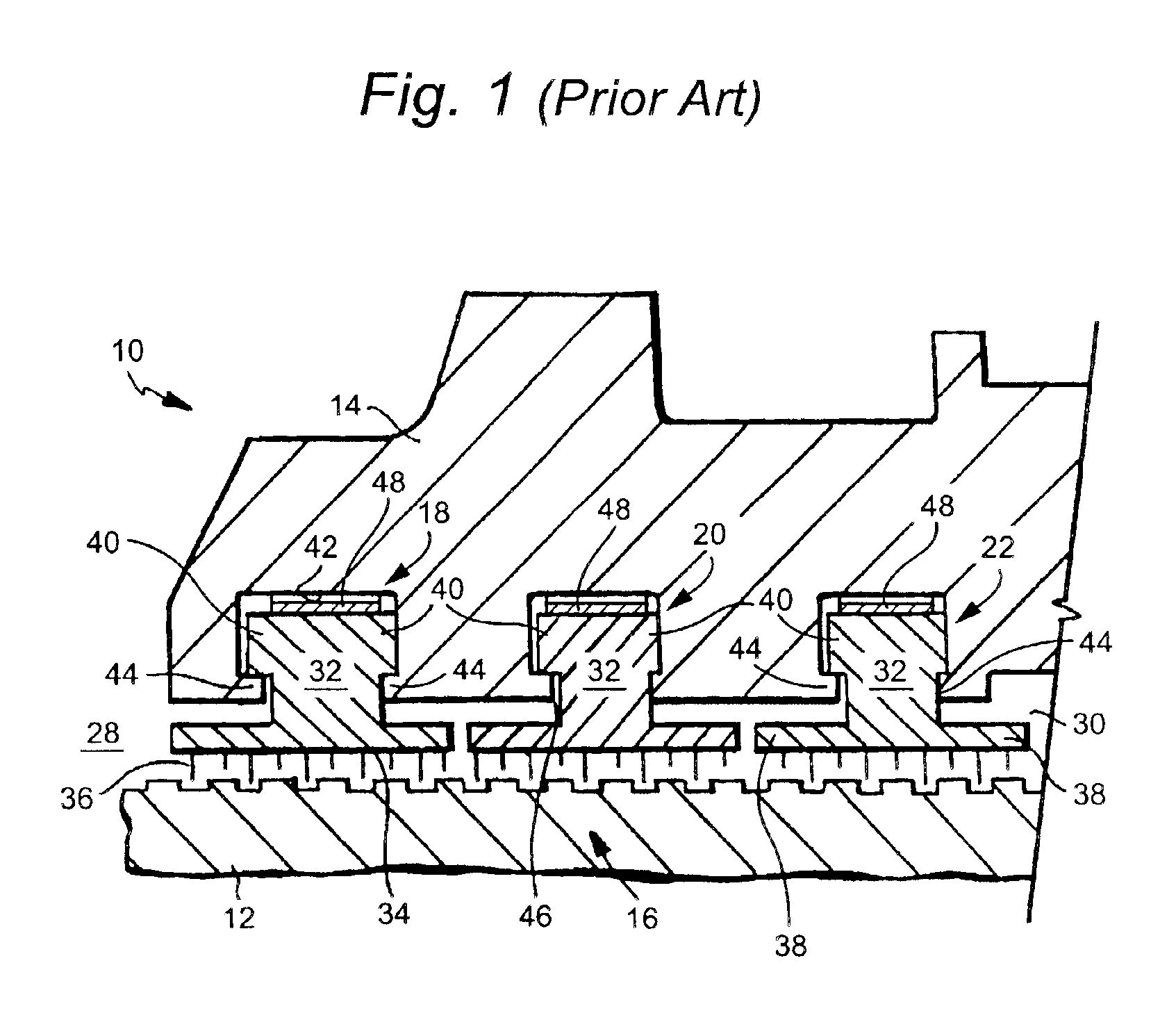
[0017]Referring now to FIG. 1, there is illustrated a portion of a steam turbine, generally designated 10, including a turbine rotor or shaft 12, disposed in a turbine housing 14. The shaft 12 is supported for rotation by conventional means, not shown, within the turbine housing. A multiple-stage labyrinth seal 16 includes a plurality of seal rings 18, 20 and 22 disposed about the turbine shaft 12 separating high and low pressure regions 28 and 30, respectively. Each seal ring is formed of an annular array of a plurality of arcuate seal segments 32. In general, the labyrinth seal 16 functions by placing a relatively large number of partial barriers to the flow of steam from the high pressure region 28 to the low pressure region 30. Each barrier forces steam, attempting to flow parallel to the axis of turbine shaft 12, to follow a tortuous path whereby a pressure drop is created. The sum of all the pressure drops in the labyrinth seal 16 is, by definition, the pressure difference bet...


PUM


Abstract

A packing spring for a steam turbine comprising a flat, elongated spring body of specified length, width and thickness dimensions; a flange at one end of the main spring body; and at least one bend in the main spring body, located substantially midway along the length dimension of the spring body.

Description

[0001]This invention relates to seals used in steam turbines and, specifically, to a spring configuration for a packing seal used between a stationary turbine component and the turbine rotor.BACKGROUND OF THE INVENTION[0002]Turbomachines use numerous sealing techniques to establish seals between stationary and rotating parts of the turbine. In some instances, the seals are designed to provide radial movement away from the rotating components to prevent rubs during operation. In other instances, the springs bias the seal segments toward the rotor, while fluid pressure applied during operation counters the spring force so as to move the seal teeth out of engagement with, but in close proximity to the rotating component to achieve the desired sealing function.[0003]In steam turbines, for example, it is customary to employ a plurality of arcuate seal ring segments to form a labyrinth seal about and between the stationary and rotating components. Typically, the arcuate seal ring segments...

Claims


Application Information

Patent Timeline
Patent Type & Authority Patents(United States)
IPC IPC(8): F16J15/44
CPCF16J15/442
Inventor ZUO, LEITURNQUIST, NORMAN ARNOLDBAILY, FREDERICK GEORGEBURNETT, MARK EDWARDFANG, BIAO
Owner GENERAL ELECTRIC CO
Why Eureka
Try Eureka