Mobile self-recovery lift chair

a lift chair and self-recovery technology, applied in the direction of wheelchairs/patient conveyance, transportation and packaging, vehicle arrangements, etc., can solve the problems of substantial drain on the healthcare system, loss of feeling in the legs, and associated costs, so as to reduce the incidence of injury, and facilitate the loading of a person.

Inactive Publication Date: 2005-08-30
BECK TERRY L
View PDF11 Cites 18 Cited by
  • Summary
  • Abstract
  • Description
  • Claims
  • Application Information

AI Technical Summary

Benefits of technology

[0023]These objects are achieved in a novel wheeled lift chair with a vertically adjusted seat to facilitate loading of a person from the floor and with hinged seat sides to facilitate loading of a person from a raised platform, such as a bed. The chair provides a mobile self-recovery lift chair that lowers to a position in contact with the floor and thus enables an individual who has fallen to the floor to get to a seated position in the chair. Because the person can enter the chair from the person's fallen position, caregivers need not lift the person into the chair, thereby decreasing the incidence of injury to caregivers incurred while attempting to lift someone from the floor.
[0024]The chair provides an improved way for an individual who has fallen to return to a seated position and then to stand or wheel to another location. The chair includes an enclosed lift frame with rear wheels for mobility, a seat that moves vertically from contact with the floor to a selective seat height. Forward wheels provide support of the chair under the seat near the chair center of gravity when loaded. A seat lift mechanism comprises a lift trolley connected to the seat and contained within the lift frame. Releasable wheel brakes actuated from a seat arm keep the chair stationary during loading and unloading. A rechargeable battery provides power for the motorized lift mechanism.
[0025]Handles on the lift frame behind the lift frame, suitable for use by an assistant when moving the chair in traditional manner, can be rotated outward as a counterbrace that the assistant uses to stabilize the chair during loading and unloading. One assistant hand is positioned on the handle while the other may be used to lift a fallen individual into the seat, thereby relieving the strain on the assistant's back, neck, and shoulders therein reducing the likelihood of injury to the assistant.
[0026]Arms on seat sides hinge from a normal vertical position to a horizontal position as a transfer board that allows the intended occupant to move from a raised position such as a bed or gurney to or from the chair by sliding over the seat side rather than standing out of the chair.

Problems solved by technology

The problem of getting people up and the costs associated with the injuries this endeavor causes is a substantial drain to the healthcare system.
These neuropathies while not life threatening do lead to loss of feeling in the legs and combined with decreases in visual acuity lead to many falls which an individual can not get up from.
When this happens and there is a spouse available to help them back up the spouse invariably gets injured, further decreasing the couples overall quality of life.
This chair lacks the ability to be moved from one location to another with the person in the chair or out.
This prior art demands that the individual be capable of walking away from the lift, which they may not be able to do.
The prior art of Hough also has serious safety issues with major shear points between the seat arms and the surrounding lifting frame where an arm or hand could be caught as the lift is raised.
The sliding protective plates used to hide the mechanical workings will eventually snag an article of clothing and cause serious injury.
The basic design of this feature may lead to binding over time due to the inherent complexity of the design.
Also the fabrics used to cover the motor and drive mechanism will create an environment where someone trying to stand is going to trap their foot between the frame and cloth and suffer another fall.
The fabric also lies in close proximity to the rotating drive mechanisms and could become wrapped in the mechanism thus rendering the chair inoperative.
A non-structural problem also exits in the prior art of Hough.
Without meeting this requirement most of the older or handicapped individuals will be denied access to this useful device due to financial reasons.
The art demonstrates that it does not provide the capability to pick someone up from the floor, nor was it intended to do so.
The prior art of Allred does not discuss a braking method to keep the chair stationary during transfers, which is a major safety concern.
They do not address the need for an individual who is alone to get up after a fall.

Method used


Image

  • Mobile self-recovery lift chair
  • Mobile self-recovery lift chair
  • Mobile self-recovery lift chair

Examples


Embodiment Construction

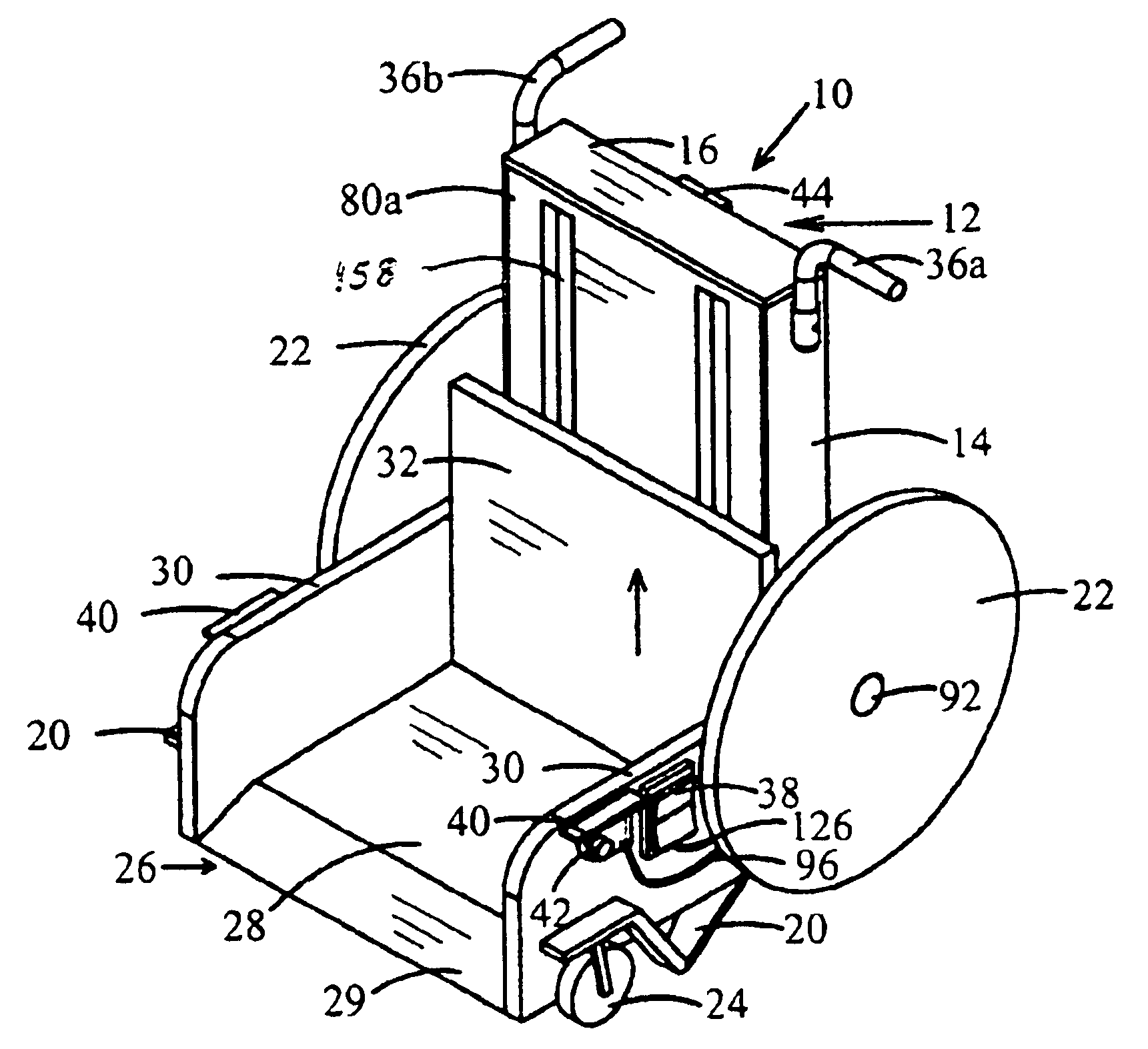
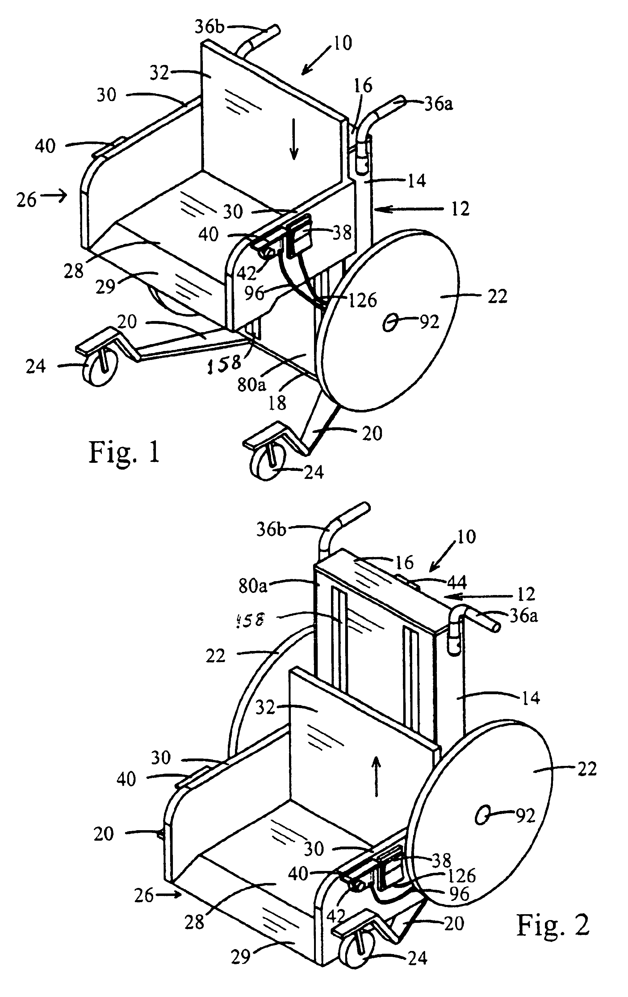
[0039]As shown primarily in FIG. 1 and FIG. 2, the lift chair 10 of the present invention comprises a lift frame 12 with rearward wheels 22 mounted rotatably on lift frame sides, a seat 26, a lift trolley 15, and forward wheels 24 also on chair sides supporting forward extending frame legs 20.

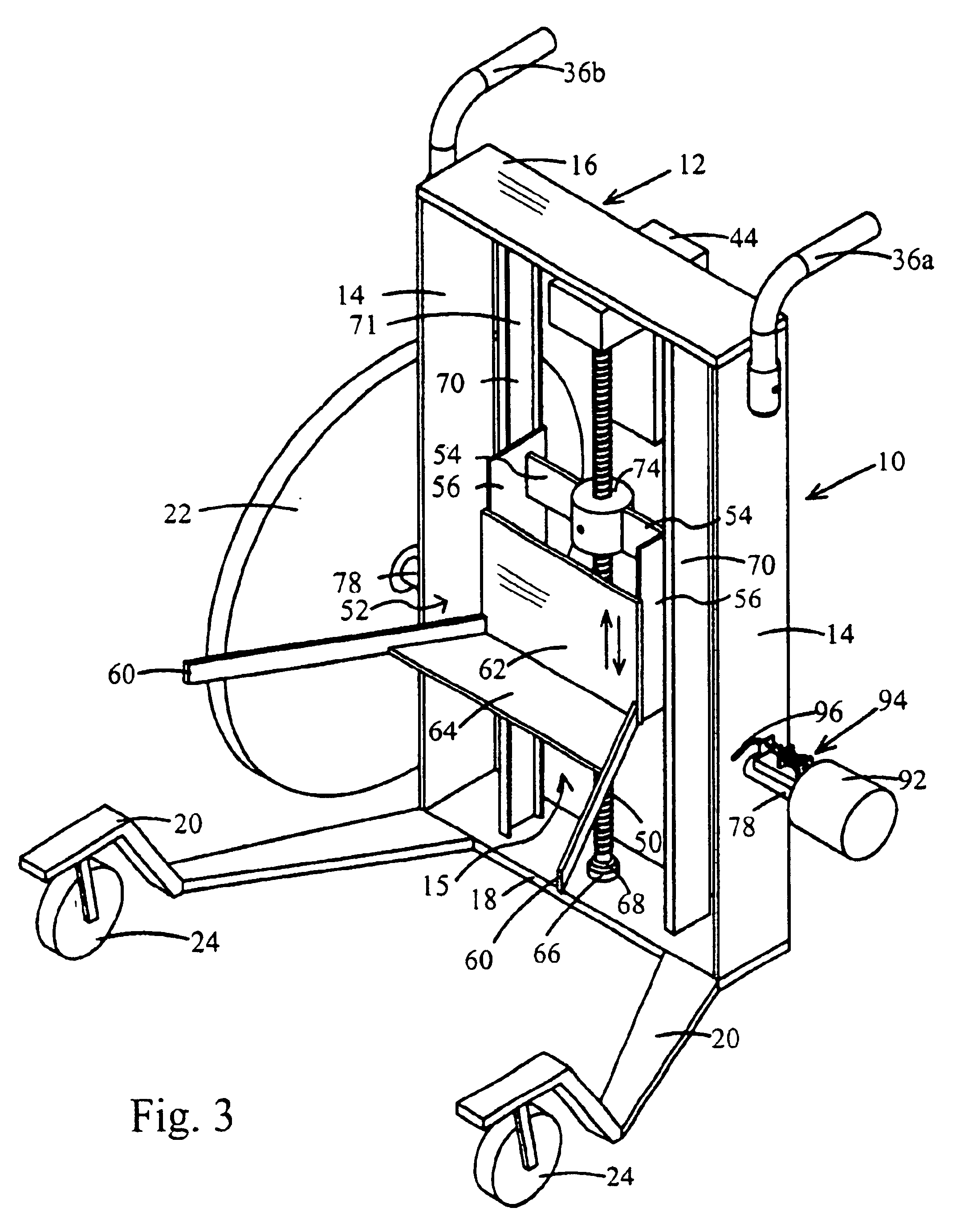
[0040]Lift frame 12 comprises upright opposing closed lift frame sides 14 spaced apart by closed bottom and top horizontal cross members 16 and 18, the frame sides and cross members having lateral extent therein forming a box-like enclosure with front and back openings, the openings covered by opposing front cover and back covers 80a and 80b on the frame sides and cross members, as shown in FIG. 6. Rear covering 80b closes the back of the lift frame 12, shielding motor 44 and lift trolley 15 from fingers and clothing and other objects.

[0041]Legs 20 extend forwardly from lift frame 12, extending horizontally under the seat 26 from the bottom cross member 18 to which it is typically attached and ...


PUM


Abstract

A self-recovery lift chair provides an improved way for an individual who has fallen to return to a seated position and then be able to stand or wheel to another location. The wheeled chair includes a lift frame and a seat suspended from a lift mechanism in the frame. The seat moves vertically from contact with the floor to variable or above normal seat heights. Seat sides fold from vertical to horizontal to serve as a loading sideboard. The lift mechanism comprises a lift trolley connected to the seat, a reversible motorized drive mechanism powered by a rechargeable battery, and a detachable actuation switch that can be operated by the user or an assistant. The lift trolley is stabilized in the frame by a vertical stabilizing rod connected on each side of a drive receiver on a central vertical threaded drive rod. Brakes keep the chair stationary until it is necessary to be moved. A pivoting handle allows the lift chair to be moved like a wheel chair or when turned outward as a support point for the assistant during manually assisted transfers.

Description

BACKGROUND[0001]1. Field of Invention[0002]This invention relates to a wheeled lift chair advantageous for an incapacitated individual who has fallen to the floor and is too weak or stiff to get up, to be able to slide himself or herself onto the seat of the lift.[0003]The invention herein also relates to assistive devices, more precisely an injury prevention device that protects healthcare providers from injuring their back, neck and shoulders while attempting to lift someone off of the floor.[0004]2. Prior Art[0005]The Center for Disease Control reported that one in three adults over the age of 65 will fall annually. One half of this group will suffer repeat falls. With each decade of life this percentage increases. They have reported that 50% of the people who fall and are unable to get up for just a few hours, will die within 6 months, and that 40% of all extended care admissions are because of repeat falls. In addition for every 1000 extended care residents there will be 1600 f...

Claims


Application Information

Patent Timeline
Patent Type & Authority Patents(United States)
IPC IPC(8): A61G5/00A61G5/10
CPCA61G5/1059A61G7/1011A61G2005/1054Y10S297/04A61G5/1054
Inventor BECK, TERRY L.
Owner BECK TERRY L
Why Eureka
Try Eureka