Noise reduction conduit for static components in aircraft engines

a static component and conduit technology, applied in the field of noise reduction structures, can solve the problems of high noise levels and world concerns, and achieve the effect of reducing the thickness of the walls of the walls with the lightest structural solution

Inactive Publication Date: 2005-08-30
SENER ING Y SISTEMAS
View PDF4 Cites 32 Cited by
  • Summary
  • Abstract
  • Description
  • Claims
  • Application Information

AI Technical Summary

Benefits of technology

The present embodiment describes an improved design where two different types of materials can be used together instead of just one type like ceramics or metal foils. This allows for better performance without adding extra material compared to traditional designs while reducing its overall size. Additionally, this new design eliminates problems such as cracks caused during use due to loading on certain parts inside these structures which could cause failure over time.

Problems solved by technology

The technical problem addressed in this patent text is the need to reduce noise in airplanes caused by the engines and high-speed airflow, while maintaining the efficiency and durability of the aircraft manufacturing process. The text describes the development of noise absorbers that can minimize their impact on engine efficiency.

Method used


Image

  • Noise reduction conduit for static components in aircraft engines
  • Noise reduction conduit for static components in aircraft engines
  • Noise reduction conduit for static components in aircraft engines

Examples


Embodiment Construction

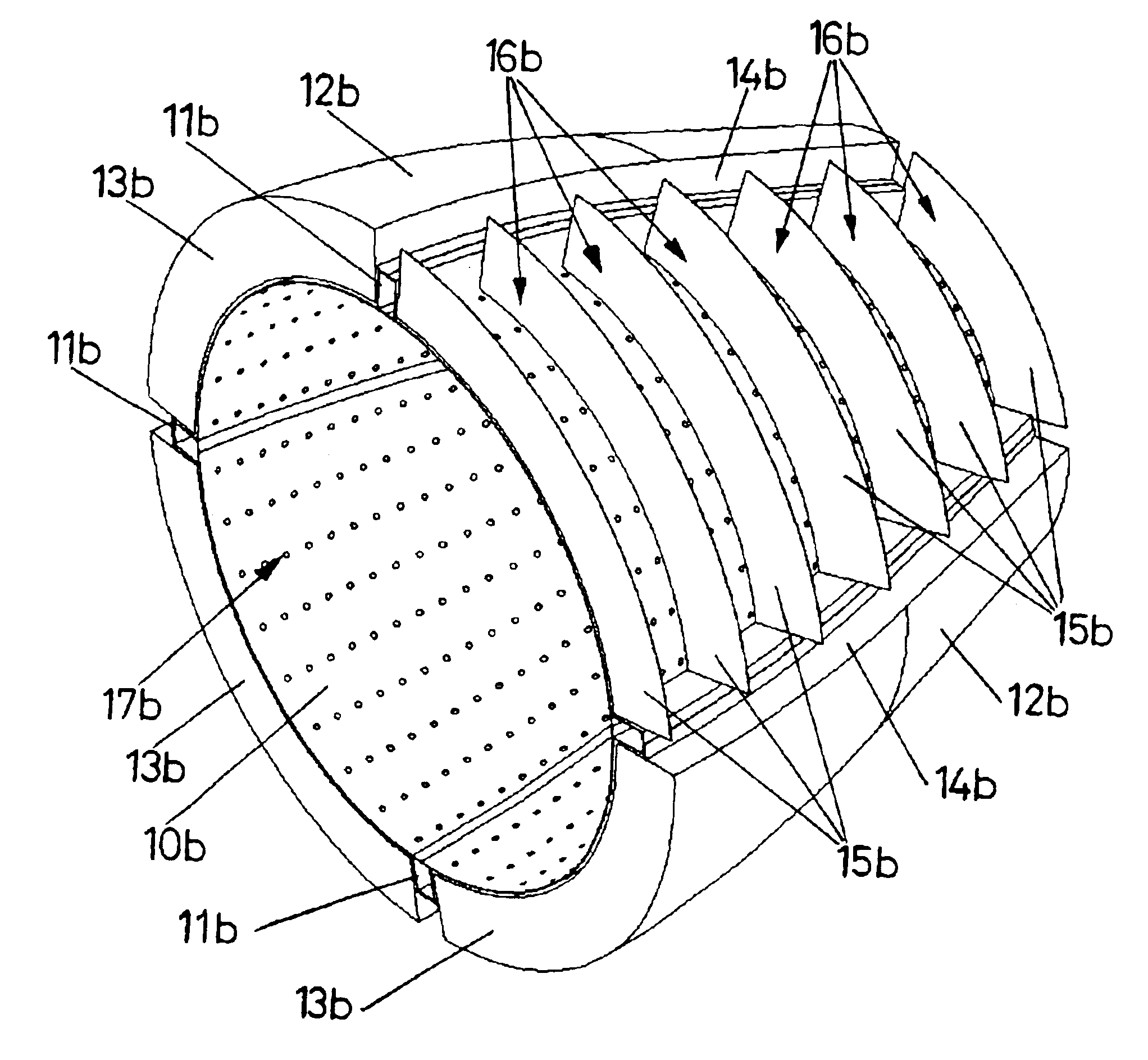
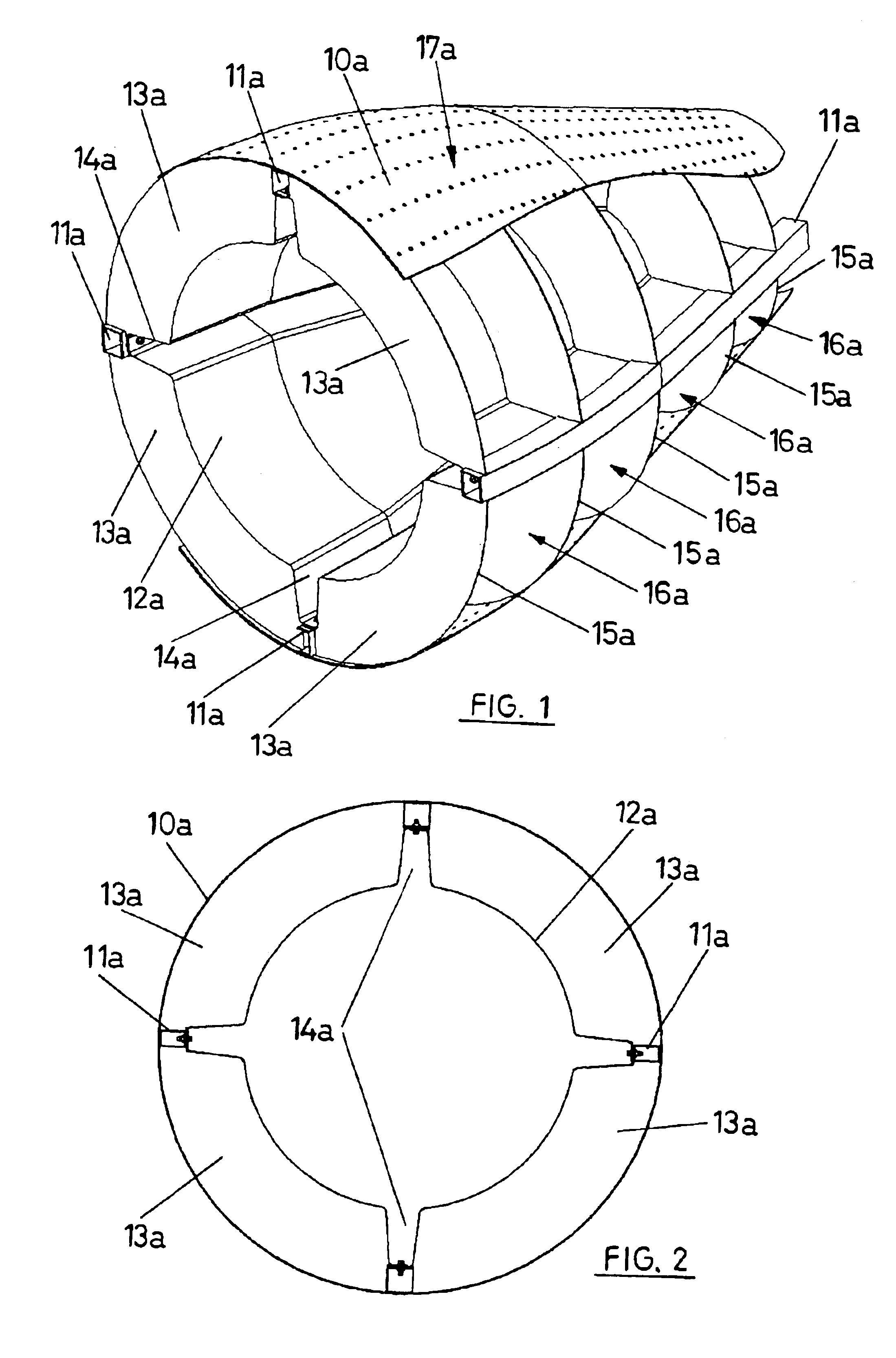
[0043]FIG. 1 shows a perspective view of an annular cone structure usually located in the exhaust area of a gas turbine engine. For improved clarity the flange where the structure is attached to the rest of the engine has been omitted, as well as the end part of the cone that has no interest from the noise reduction point of view.

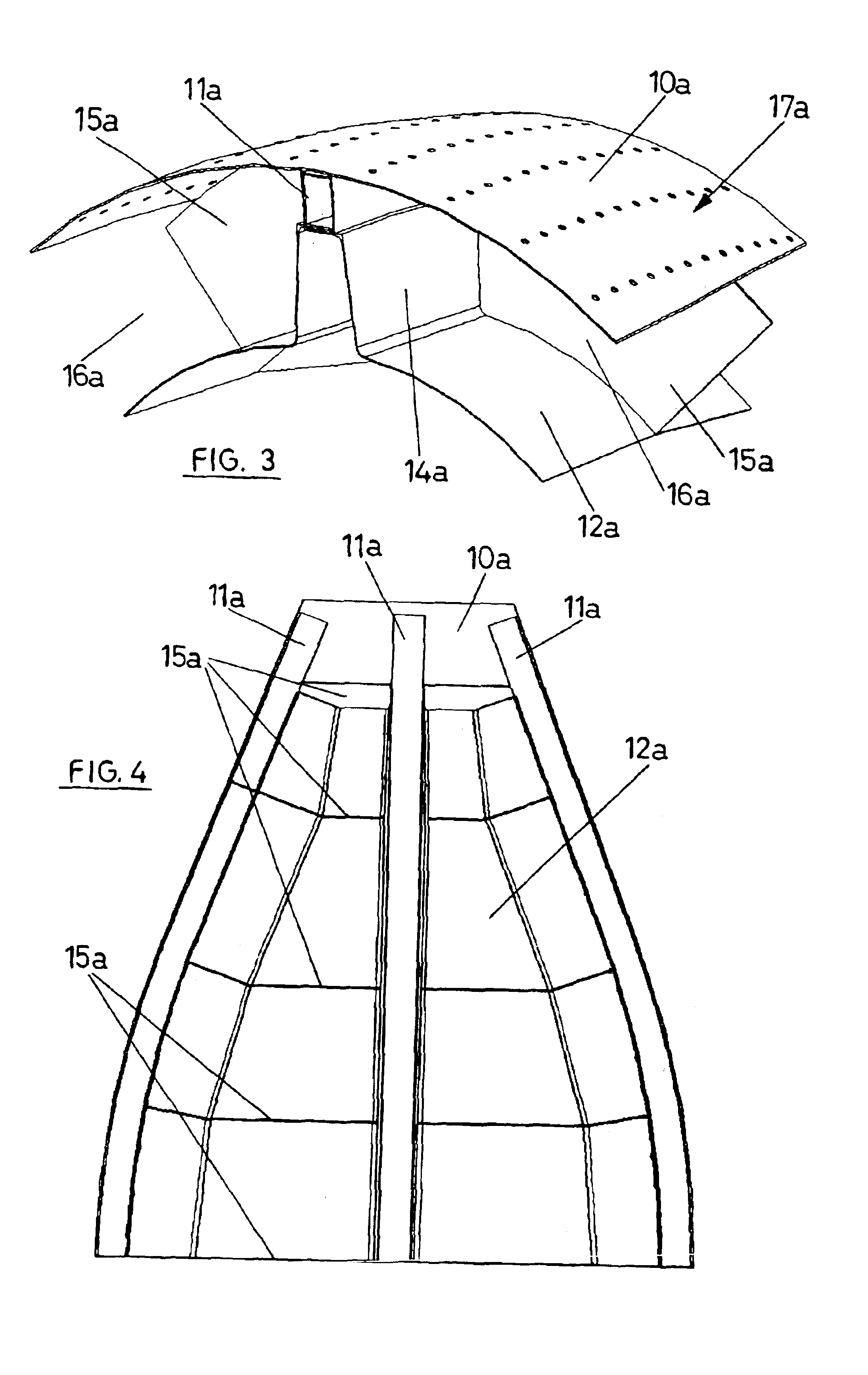
[0044]The noise reduction conduit includes an outer wall, or aerodynamically wet wall, 10a that follows an aerodynamic profile defined by the aerodynamic requirements imposed by the engine.

[0045]This outer wall is perforated with a density and size of holes 17a defined according to the acoustic requirements of the specific application.

[0046]The outer wall is completed with a series of intermediate resistant elements or stiffeners 11a that are disposed in the axial direction.

[0047]The outer wall 10a will be secured to the stiffeners 11a through a mechanical joint using screws and nuts or rivets. Other joining methods can be used too, as welding, brazing or b...


PUM

PropertyMeasurementUnit
Temperatureaaaaaaaaaa
Weightaaaaaaaaaa
Structureaaaaaaaaaa

Abstract

Noise reduction conduit for non rotary components of aircraft engines, subjected to a characteristic range of temperatures of a gas turbine engine, constituted by an annular structure composed of an aerodynamic wet wall (10a, 10b), perforated and resistant mechanically and thermally; of a dry wall (12a, 12b), not resistant and of light weight; and of some intermediate elements to which both walls are mechanically attached and that define a jump or difference of temperature between the wet and dry walls; between which wet (10a, 10b) and dry walls (12a, 12b) there are partitions that define cavities (16a, 16b) isolated with regard to each other.

Description


Claims


Application Information

Patent Timeline
Owner SENER ING Y SISTEMAS
Why Eureka
Try Eureka