Filter for the separation of contaminants from gas stream

Inactive Publication Date: 2005-08-30
BEKO TECHNOLOGIES GMBH
View PDF6 Cites 95 Cited by
  • Summary
  • Abstract
  • Description
  • Claims
  • Application Information

AI Technical Summary

Benefits of technology

[0005]It is the object of the invention to thoroughly develop the previously known filter so that it is easier to manufacture and more

Problems solved by technology

It cannot be ruled out that said ring is subjected to such a load during insertion that it slips out of its holding device.
Another disadvantage of the previously known filter is that a differential pressure measurement between inlet and outlet is difficult.
This makes the mechanical implementation complicated and the additional sealing requires specia

Method used


Image

  • Filter for the separation of contaminants from gas stream
  • Filter for the separation of contaminants from gas stream
  • Filter for the separation of contaminants from gas stream

Examples


Embodiment Construction

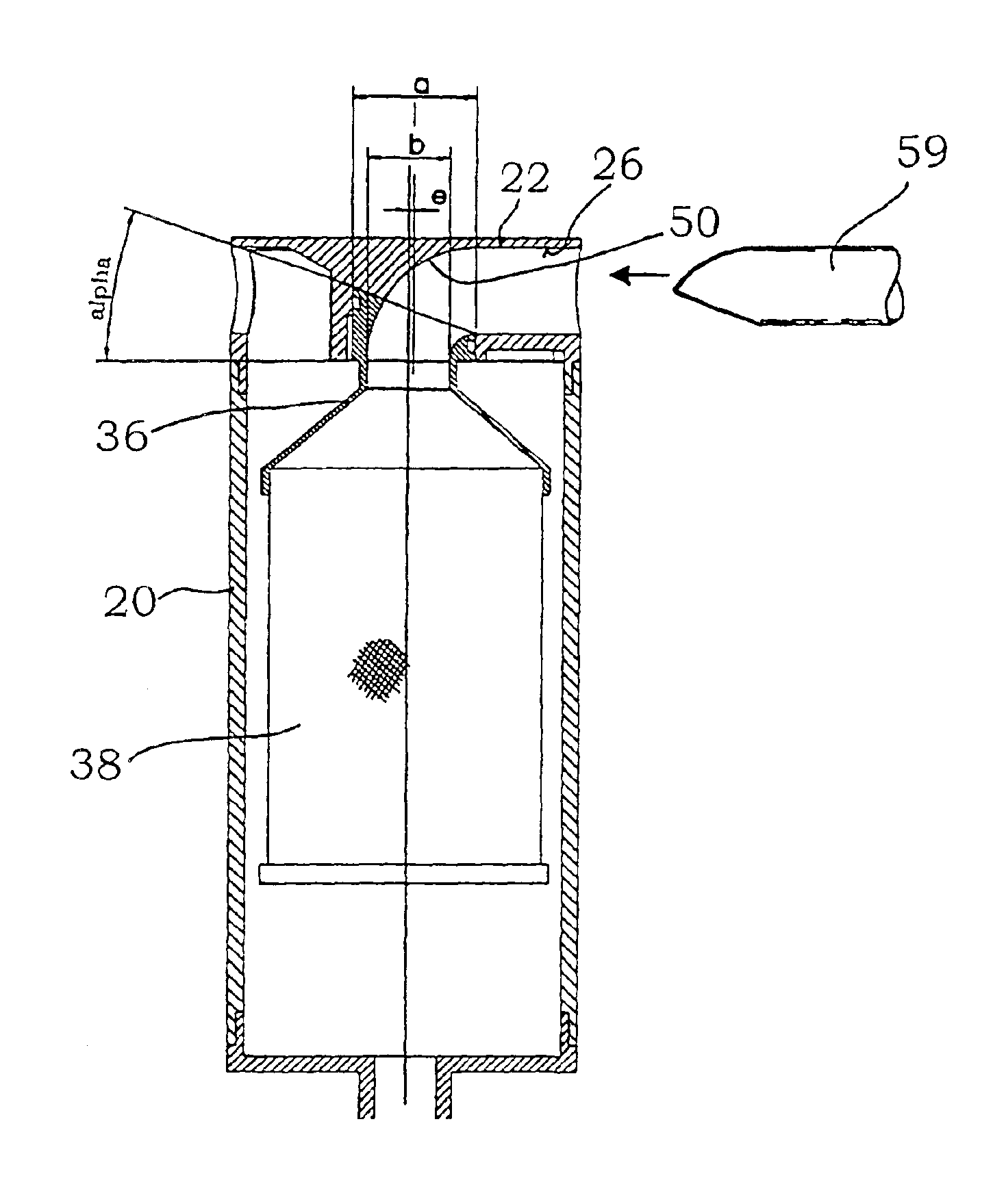
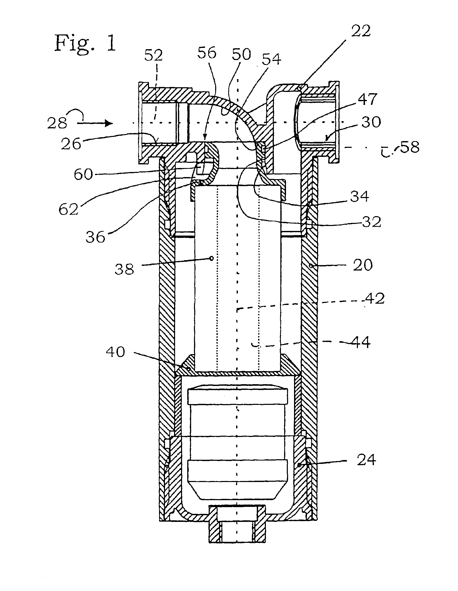
[0030]As can be surveyed from FIG. 1, the filter has a multi-piece housing. The housing has a housing body portion 20, a housing head portion 22 and a housing bottom portion 24. The housing head portion 22 is provided with an inlet 26 for the gas stream to be cleaned, see arrow 28, and with an outlet 30. The outlet must not necessarily be formed within the housing head portion. The housing head portion 22 further has a first sealing surface 32 which in the present case is formed by a portion of the inner wall of a cylindrical receiving bore 34.

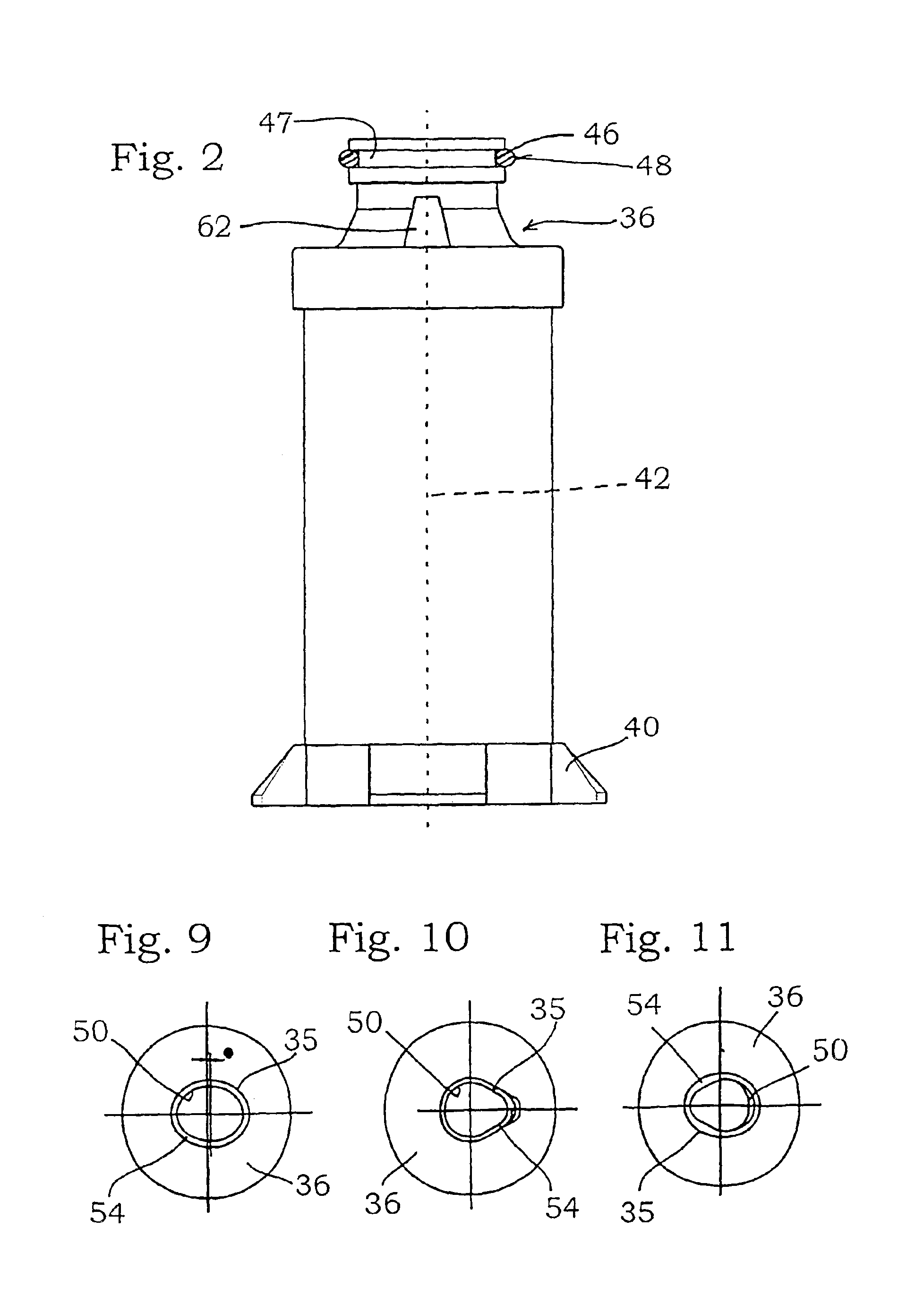
[0031]The housing accommodates a filter element. It has an element head 36, a tubular element body 38 and an element bottom 40. Beneath the element bottom 40 there is room for an additional device such as a condensate drain device.

[0032]The element body 38 has a central element axis 42 and an element inner volume 44 which is cylindrical and centered on the element axis 32.

[0033]The element body 38 may be any configuration. Oval-shaped element ...


PUM

PropertyMeasurementUnit
Angleaaaaaaaaaa
Angleaaaaaaaaaa
Angleaaaaaaaaaa

Abstract

A filter for separating contaminants from a gas stream, including (a) a housing having a housing body and a housing head, the housing head having an inlet for the gas stream to be purified, an outlet and a first sealing surface, and (b) a filter element accommodated in the housing, having an element head and an element body having a central element axis and an element interior. The element head has a second sealing surface which cooperates with the first sealing surface. A curved inlet manifold is formed between the inlet and the element interior. The inlet manifold is embodied partly in the housing head and partly in the element head such that the first and second sealing surfaces contact in a sealing plane at a 90° to 60° angle to the element axis. A radially arranged seal is provided on the sealing plane, forming one of the sealing surfaces.

Description

FIELD OF THE INVENTION[0001]The invention relates to a filter for separating impurities from a gas stream with a) a multi-piece housing, said housing having a housing body portion and a housing head portion, the housing head portion having an inlet for the gas stream to be cleaned and an outlet, and the housing head portion having further a first sealing surface, and b) with a filter element accommodated within said housing, said filter element having an element head and a tubular element body which element body has a central element axis and an element inner volume, said element head having a second sealing surface that releasably cooperates with the first sealing surface and a curved inlet elbow being configured between the inlet and the element inner volume.BACKGROUND OF THE INVENTION[0002]Such a filter is known from WO 99 / 30799. In this previously known filter, the element head forms the complete inlet elbow. It is immediately adjacent to the inlet. Accordingly, the housing head...

Claims


Application Information

Patent Timeline
IPC IPC(8): B01D46/24B01D46/00
CPCB01D46/0012B01D46/0043B01D46/2414B01D2201/296B01D2271/027
Inventor SCHLENSKER, HERBERTSINSTEDTEN, JOHANNES
Owner BEKO TECHNOLOGIES GMBH
Why Eureka
Try Eureka