
Adaptive beamforming apparatus and method

a beamforming apparatus and beam technology, applied in the field of adaptive beamforming apparatus and method, can solve the problems of difficult to employ the lms algorithm in fast fading radio environment, slow convergence speed of adaptive beamforming methods, and various problems

Inactive Publication Date: 2005-08-30
LG ELECTRONICS INC
View PDF4 Cites 51 Cited by
  • Summary
  • Abstract
  • Description
  • Claims
  • Application Information

AI Technical Summary

Benefits of technology

[0015]It is another object of the present invention to provide an adaptive beamforming apparatus and method capable of producing an optimum beam pattern by accurately estimating the AOA spectrum.
[0016]It is another object of the present invention to provide an adaptive beamforming apparatus and method capable of improving a system capacity and communication quality by generating an optimum beam pattern to a mobile terminal.

Problems solved by technology

The related art adaptive beamforming methods have various problems.
Hence, it is difficult to employ the LMS algorithm in fast fading radio environments.
Additionally, with regard to CMA, since it is a blind adaptive algorithm, its convergence speed is slower than those algorithms that use the training signals.
Also, the convergence characteristics of the CMA are not precisely defined relative to the LMS algorithm.
Even though there exist various other beamforming algorithms, most of them are much too complex to apply to the radio systems, as compared to the LMS and CMA.
Accordingly, such algorithms are problematic.

Method used


Image

  • Adaptive beamforming apparatus and method
  • Adaptive beamforming apparatus and method
  • Adaptive beamforming apparatus and method

Examples


Embodiment Construction

[0028]A preferred embodiment of the present invention will be described hereinafter with reference to the accompanying drawings.

[0029]The uplink dedicated physical channel (DPCH) defined by the 3GPP comprises three-layer structure of a super-frame, a radio frame, and a slot. There are two types of DPCHs. The first type is a dedicated physical data channel (DPDCH) for transferring, dedicated data and the second type is a dedicated physical control channel (DPCCH) for transferring control information.

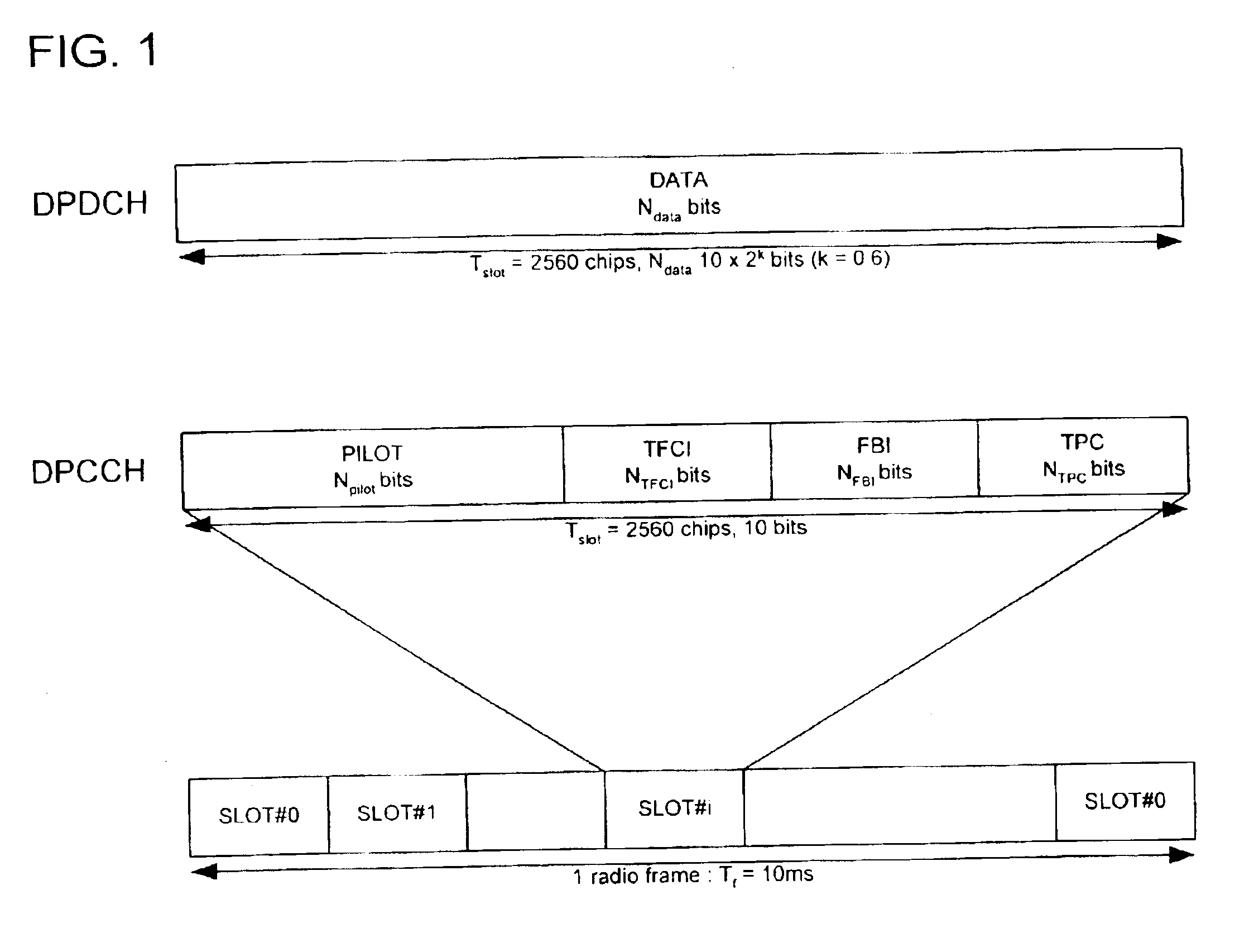
[0030]FIG. 1 illustrates an uplink radio frame structure according to the 3GPP RAIN specification as used by the preferred embodiment.

[0031]As shown in FIG. 1, an uplink DPCH radio frame includes a plurality of slots (slot#0-slot#14). A DPCCH slot includes a pilot field, a transport format combination indicator (TFCI) field, a format byte integer (FBI) field, and a transmit power control (TPC) field.

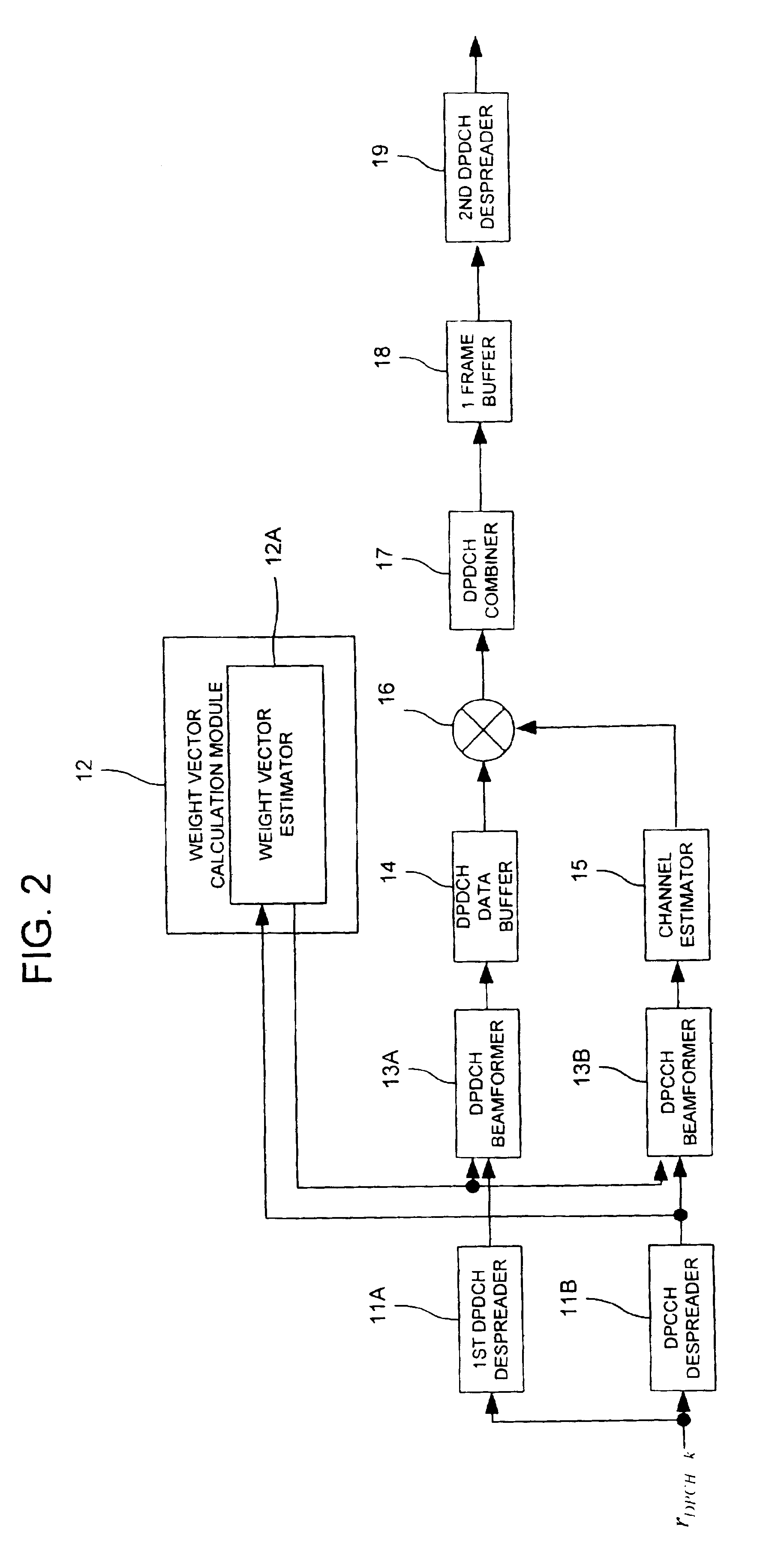
[0032]FIG. 2 illustrates an adaptive beamforming apparatus according to a preferred embodi...


PUM


Abstract

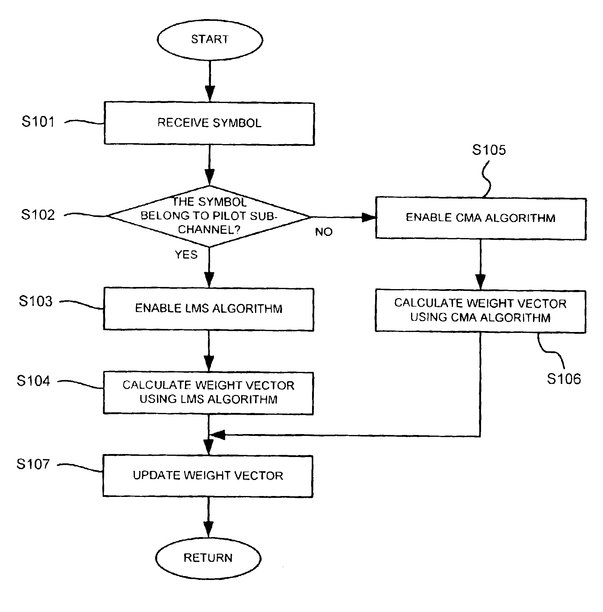
Disclosed are an adaptive beamforming apparatus and method that despreads an input signal, and determines whether a symbol of despread signal belongs to a pilot sub-channel or non-pilot sub-channel of the despread signal. One of two beamforming algorithms is accordingly enabled. If the symbol belongs to the pilot sub-channel, a first algorithm is used to calculate a weight vector, and if the symbol belongs to the non-pilot sub-channel, a second algorithm is used to calculate the weight vector. A current weight vector is updated using newly calculated weight vector, and a beam pattern is formed based on the updated weight vector.

Description

BACKGROUND OF THE INVENTION[0001]1. Field of the Invention[0002]The present invention relates to an adaptive beamforming apparatus and method, and in particular to an improved weight vector update technique for the adaptive beamforming apparatus and method.[0003]2. Background of the Related Art[0004]In wireless communication systems, various diversity methods are used to increase the coverage area and capacity of a system. For example, use of a rake receiver architecture provides an effective immunity to the inter-symbol interference (ISI) in multipath propagation environments that cause the same signal to be repeatedly received at an antenna at a plurality of different time intervals.[0005]Recently, directive antennas have been used to increase the signal-to-noise ratio (SNR) by increasing the energy radiated to a desired mobile terminal while simultaneously reducing the interference energy radiated to other remote mobile terminals. Such reduction in the interference energy radiate...

Claims


Application Information

Patent Timeline
IPC IPC(8): H04B7/04H04B7/08H04B1/69
CPCH04B7/0408H04B7/0854H04B7/086H04B1/712
Inventor KIM, SANG-CHOON
Owner LG ELECTRONICS INC
Learn More