Apparatus and method for delay bound weighted round robin cell scheduling in asynchronous transfer mode switch

Inactive Publication Date: 2005-08-30
USRCOM KOREA
View PDF5 Cites 8 Cited by
  • Summary
  • Abstract
  • Description
  • Claims
  • Application Information

AI Technical Summary

Benefits of technology

[0024]In accordance with another aspect of the present invention, there is provided a method for DBWRR (Delay Bound Weighted Round Robin) cell scheduling in an ATM (Asynchronous Transfer Mode) switch, comprising the steps of (a) allowing a queuing module to receive high-speed ATM cells, group the received ATM cells according to scheduling cycles on a link basis and store the resulting ATM cell groups in a specific one of a plurality of input buffers; (b) allowing an ATM processor to store cell scheduling information about the ATM cell groups stored in the specific input buffer, in a specific one of a plurality of ATM cell scheduling tables, corresponding to the specific input buffer; (c) allowing the ATM processor to recognize the cell scheduling information about a first one of the ATM cell groups stored in the specific input buffer, from the specific ATM cell scheduling table; (d) allowing the ATM processor to calculate a

Problems solved by technology

Up until recently, because of economical and technical problems, little interest has been aroused in studies of provision of existing telephone-class voice and facsimile services, such as a POTS (Plain Old Telephone Service), over an ATM network.
In this regard, the cell transfer delay has a great effect on the quality of service.
However, the above-mentioned DRR cell scheduling method does not consider either a connection delay or cell loss.
In this connection, the application of the DRR cell scheduling method to the VTOA of the IMT-2000 system disadvantageously necessitates the introduction of an algorithm considering data delays occurring during cell transfer, such as a packet fill delay (PFD), transfer delay and queuing delay, and an algorithm for discarding cells violating delay requirements.
However, the ATM cell scheduling in the above manner is desirable to guarantee the quality of service with respect to traffic with a constant cell generation rate, such as constant bit rate (CBR) traffic, but has difficulties in guaranteeing the quality of service and efficiently using a network bandwidth, with respect to

Method used


Image

  • Apparatus and method for delay bound weighted round robin cell scheduling in asynchronous transfer mode switch
  • Apparatus and method for delay bound weighted round robin cell scheduling in asynchronous transfer mode switch
  • Apparatus and method for delay bound weighted round robin cell scheduling in asynchronous transfer mode switch

Examples


Embodiment Construction

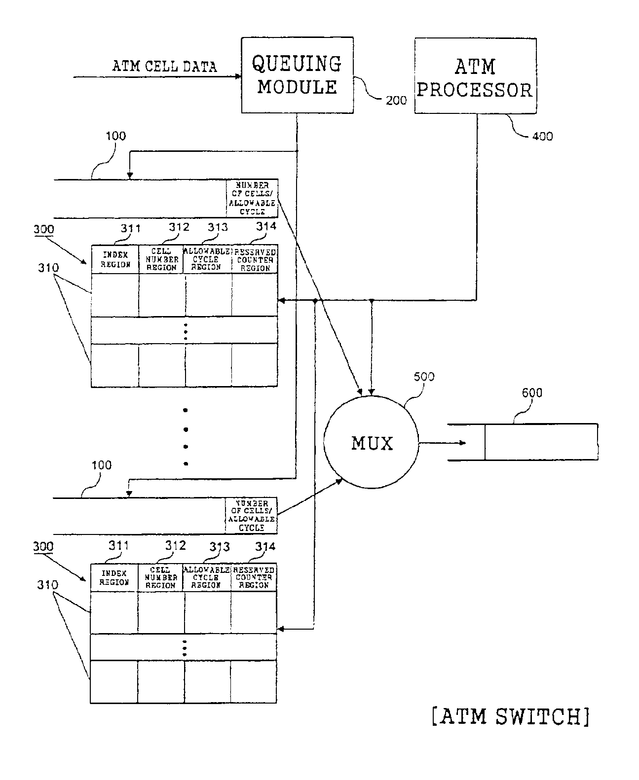
[0032]With reference to FIG. 3, there is shown in block form the construction of an apparatus for DBWRR cell scheduling in an ATM switch in accordance with a preferred embodiment of the present invention. As shown in this drawing, the DBWRR cell scheduling apparatus comprises a plurality of input buffers 100, a queuing module 200, a plurality of ATM cell scheduling tables 300, an ATM processor 400, a Mux 500 and an output buffer 600.

[0033]The input buffers 100 are memories for storing high-speed ATM cell groups written by the queuing module 200 in order.

[0034]The queuing module 200 acts to receive high-speed ATM cells from a block just upstream of the system (for example, a switch or router), group the received ATM cells according to scheduling cycles on a link basis and store the resulting ATM cell groups in the input buffers 100. In the present embodiment, if time from one service reception to the next service reception in a connection i is defined as RPi (Round Robin Period), cel...


PUM


Abstract

An apparatus and method for DBWRR (Delay Bound Weighted Round Robin) cell scheduling in an ATM (Asynchronous Transfer Mode) switch. More particularly, the present invention provides an apparatus and method for DBWRR cell scheduling in a high-speed ATM switch which can meet requirements for a cell transfer delay of real-time traffic in the ATM switch and minimize a processing overhead of the switch.

Description

CROSS REFERENCE TO RELATED APPLICATIONS[0001]This application claims priority from Korean Application No. 2000-59217, filed Oct. 9, 2000, which is hereby incorporated by reference.BACKGROUND OF THE INVENTION[0002]1. Field of the Invention[0003]The present invention relates in general to an apparatus and method for DBWRR (Delay Bound Weighted Round Robin) cell scheduling in an ATM (Asynchronous Transfer Mode) switch, and more particularly to an apparatus and method for DBWRR cell scheduling in a high-speed ATM switch which can meet requirements for a cell transfer delay of real-time traffic in the ATM switch and minimize a processing overhead of the switch.[0004]2. Description of the Related Art[0005]Up until recently, because of economical and technical problems, little interest has been aroused in studies of provision of existing telephone-class voice and facsimile services, such as a POTS (Plain Old Telephone Service), over an ATM network.[0006]Recently, however, with the developm...

Claims


Application Information

Patent Timeline
IPC IPC(8): H04Q11/04H04L12/56H04L49/111H04L12/28
CPCH04L49/3081H04Q11/0478H04L2012/5649H04L2012/5679H04L2012/5681H04L12/28
Inventor KIM, DAE SIK
Owner USRCOM KOREA
Why Eureka
Try Eureka