Apparatus and method of correcting deformation of gas turbine blade

Active Publication Date: 2005-09-06
KK TOSHIBA
View PDF18 Cites 14 Cited by
  • Summary
  • Abstract
  • Description
  • Claims
  • Application Information

AI Technical Summary

Benefits of technology

[0009]An object of the present invention is to substantially eliminate defects or drawbacks encountered in the prior art mentioned

Problems solved by technology

Gas turbine blades for generators are used under severe conditions, and for this reason, the material of the gas turbine blades deteriorates and deforms during a long time operation.
However, as the HIP material regeneration treatment utilizes an isotropic pressing technology by using gas, it is impossible to correct the deformation.
Therefore, much time and cost are taken to adjust the arrangement, and even if the contact area is secured by the adjustment, it is difficult to entirely adjust the balance of gas turbine blades.
In addition

Method used


Image

  • Apparatus and method of correcting deformation of gas turbine blade
  • Apparatus and method of correcting deformation of gas turbine blade
  • Apparatus and method of correcting deformation of gas turbine blade

Examples


first embodiment

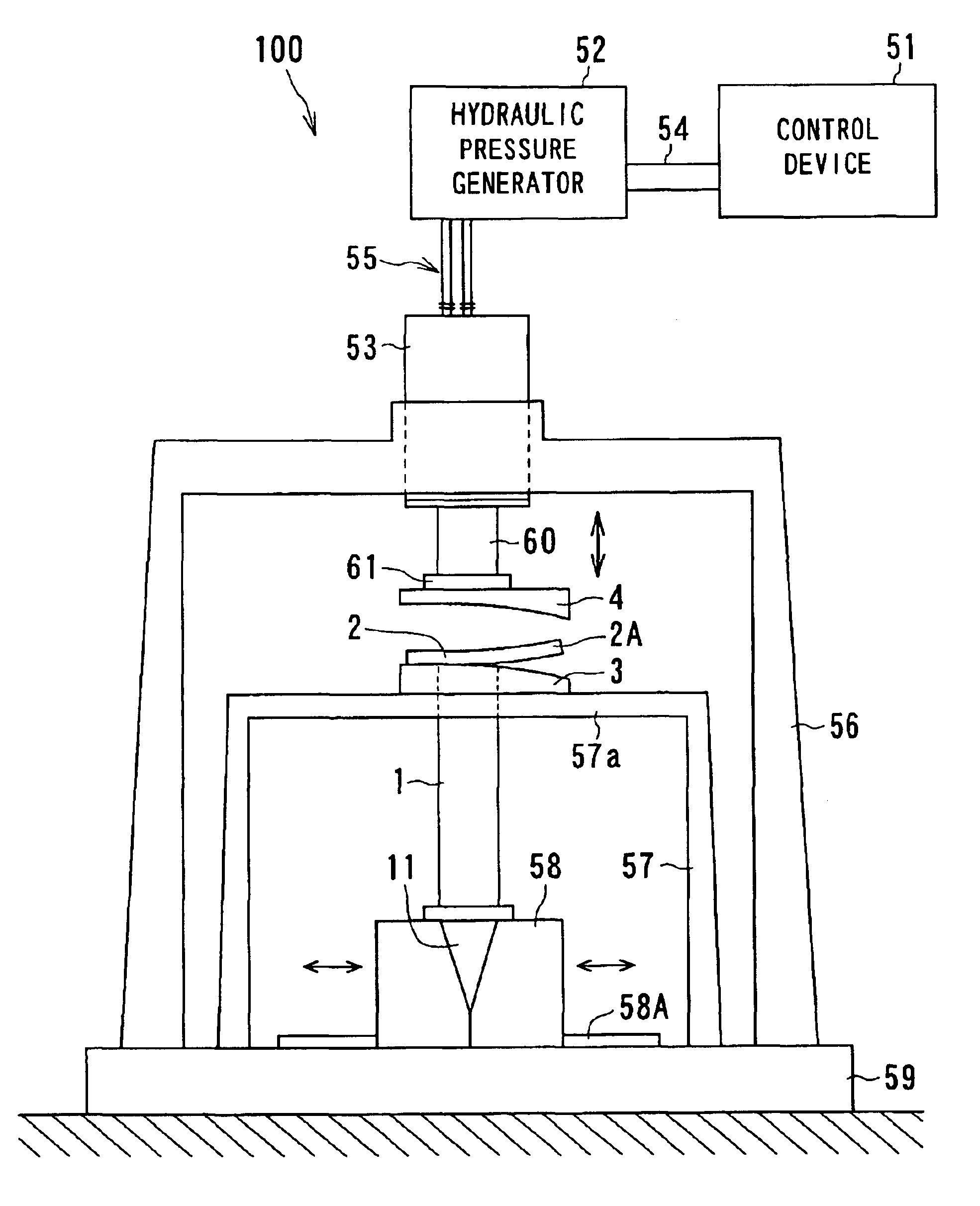
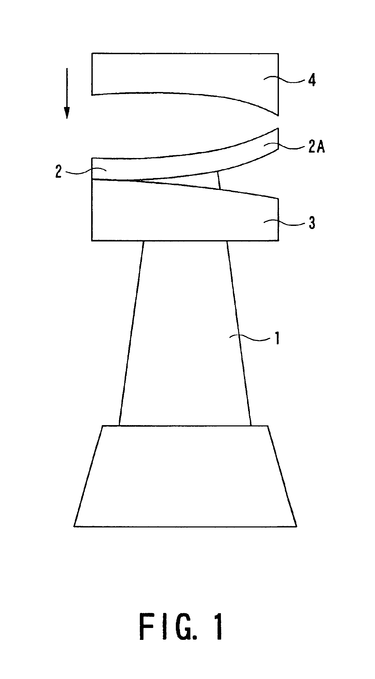
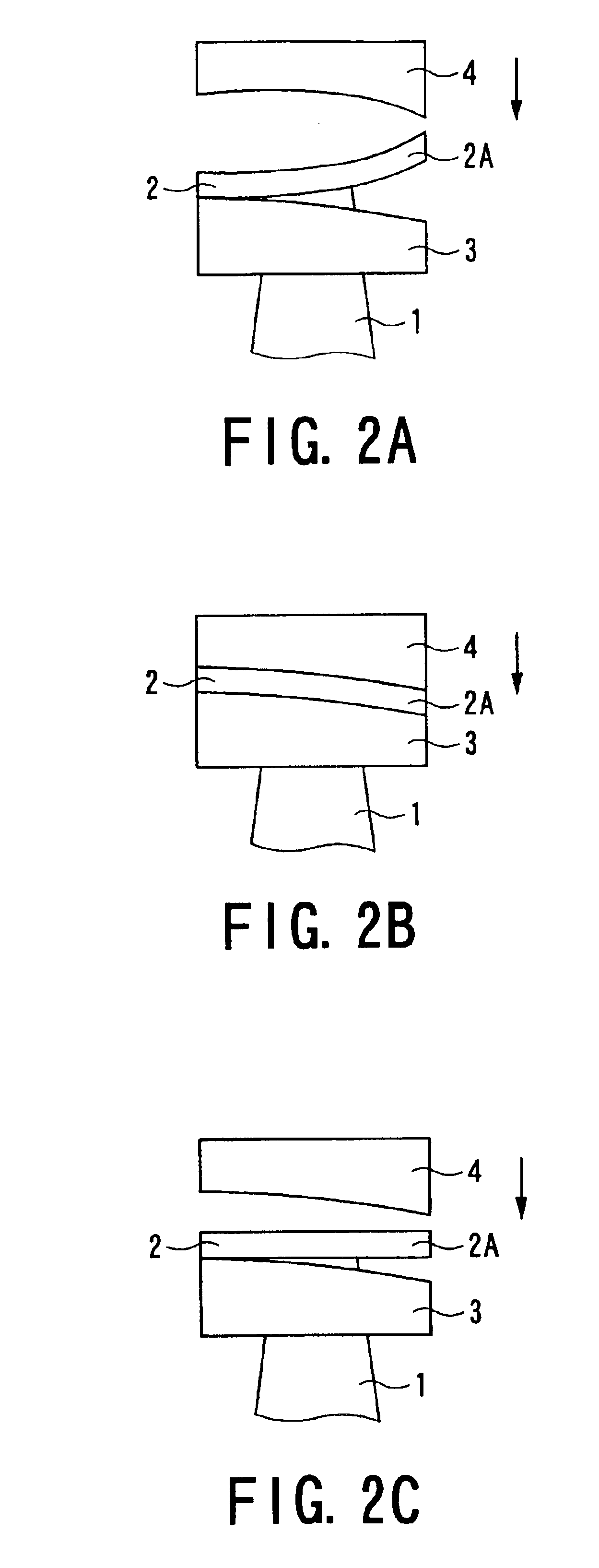
[0054]Referring to FIG. 1 representing the blade deformation correction apparatus of the present invention, the deformation correction apparatus includes a stationary die 3 for fixing a tip shroud 2 of a gas turbine blade 1 and a pressing die 4 for pressing the tip shroud 2. The stationary die 3 is arranged to a lower side of the pressing die 4 at the time of deformation correction. In order to correct a deformed portion 2A of the tip shroud 2, the tip shroud 2 is pressed between the stationary die 3 and the die 4 so that the deformed portion 2A can be corrected so as to provide a flat shape.

[0055]When correcting the deformed portion 2A of the tip shroud of the gas turbine blade 1, the gas turbine blade 1 is held between stationary die 3 (composed of two sections for front and back side surfaces of the blade) to be entirely fixed thereto. That is, the stationary die 3 has a two-divided structure, and the inner surfaces of the divided two stationary die sections are formed so as to c...

second embodiment

[0088]Further, in this second embodiment, in the control device 51, moment force acting to the boundary portion of the deformed portion 2A of the tip shroud 2 corresponding to the main and first die sections 4a and 4b is calculated, and the control signal is given to the cylinder 53B pressing the first die section 4b in consideration of this moment force so as not to cause any crack to the deformed portion 2A. Under the state, the second die section 4c is pressed, at which in the control device 51, moment force acting to the boundary portion of the deformed portion 2A of the tip shroud 2 corresponding to the first and second die sections 4b and 4c is calculated, and the control signal is given to the cylinder 53C pressing the second die section 4c in consideration of this moment force so as not to cause any crack to the deformed portion 2A. Furthermore, under this state, the third die section 4d is pressed, at which in the control device 51, moment force acting to the boundary porti...

third embodiment

[0090]the present invention will be described hereunder with reference to FIG. 9 and FIG. 10.

[0091]In the third embodiment, the stationary die 3 is divided into two or more blocks, in addition to the second embodiment shown in FIG. 9. Blocks, that is, die sections 3a to 3d are independently pressed against the back surface of the tip shroud 2 in succession to thereby correct the deformation of the tip shroud 2.

[0092]As shown in FIG. 9, the stationary die 3 and the pressing die 4 are individually divided into or composed of two or more blocks. In the embodiment of FIG. 9, the stationary die 3 is divided into four sections, that is, a stationary die main section 3a, a first die section 3b, a second die section 3c and a third die section 3d. On the other hand, as mentioned before, the pressing die 4 is divided into four sections, that is, a pressing die main section 4a, a first die section 4b, a second die section 4c and a third die section 4d.

[0093]In the deformation correction appar...


PUM

PropertyMeasurementUnit
Pressureaaaaaaaaaa
Deformation enthalpyaaaaaaaaaa
Displacementaaaaaaaaaa

Abstract

An apparatus for correcting deformation of a gas turbine blade includes a stationary die fixed to a backside of a tip shroud of a gas turbine blade to hold a back surface thereof and a pressing die pressing a front surface of the tip shroud so as to press the tip shroud of the blade between the pressing die and the stationary. A hydraulic drive mechanism including pressure generator is arranged for pressing the pressing die against the tip shroud held by the stationary die and a control device is operatively connected to the hydraulic drive mechanism so as to set and indicate a driving condition on a basis of deformation correction data preliminarily stored in the control device.

Description

BACKGROUND OF THE INVENTION[0001]1. Industrial Field of the Invention[0002]The present invention relates to apparatus for and method of correcting deformation of a gas turbine blade, capable of correcting or adjusting the deformation of a tip shroud of the gas turbine blade used for a generator by using a press.[0003]2. Related Art[0004]Gas turbine blades for generators are used under severe conditions, and for this reason, the material of the gas turbine blades deteriorates and deforms during a long time operation. Since the gas turbine blade is made of expensive heat resisting alloy, it is desirable in an economical viewpoint to repair and reuse deteriorated or deformed gas turbine blade as much as possible without discarding or newly manufacturing the blade. Regeneration by an HIP (Hot Isostatic Pressing) material reproduction treatment has been tried with respect to the material deterioration, and some extent of effect has been obtained.[0005]On the other hand, without carrying ...

Claims


Application Information

Patent Timeline
IPC IPC(8): B21D3/16B21D3/00B21D53/78B21D53/00B23P6/00F01D25/00B21D3/10F01D5/12F02C7/00
CPCB21D3/16B21D53/78F01D25/285B23P6/002Y10T29/49318Y10T29/49325B21D3/10F01D5/12F02C7/00
Inventor FUSE, TOSHIAKISAITO, DAIZOYOSHIOKA, YOMEIHIRAGISHI, MASAHIROISHII, JUNJI
Owner KK TOSHIBA
Why Eureka
Try Eureka