Sensing device and method for measuring features in a fluid
a technology of sensing device and fluid, which is applied in the direction of sensors, volume/mass flow by thermal effects, tube connectors, etc., can solve the problems of high cost of chip mounting, catheter needs to be very thin, and the wires to be soldered to the pads are expensive processes, so as to achieve the effect of easy and cheaper production
- Summary
- Abstract
- Description
- Claims
- Application Information
AI Technical Summary
Benefits of technology
Problems solved by technology
Method used
Image

Examples
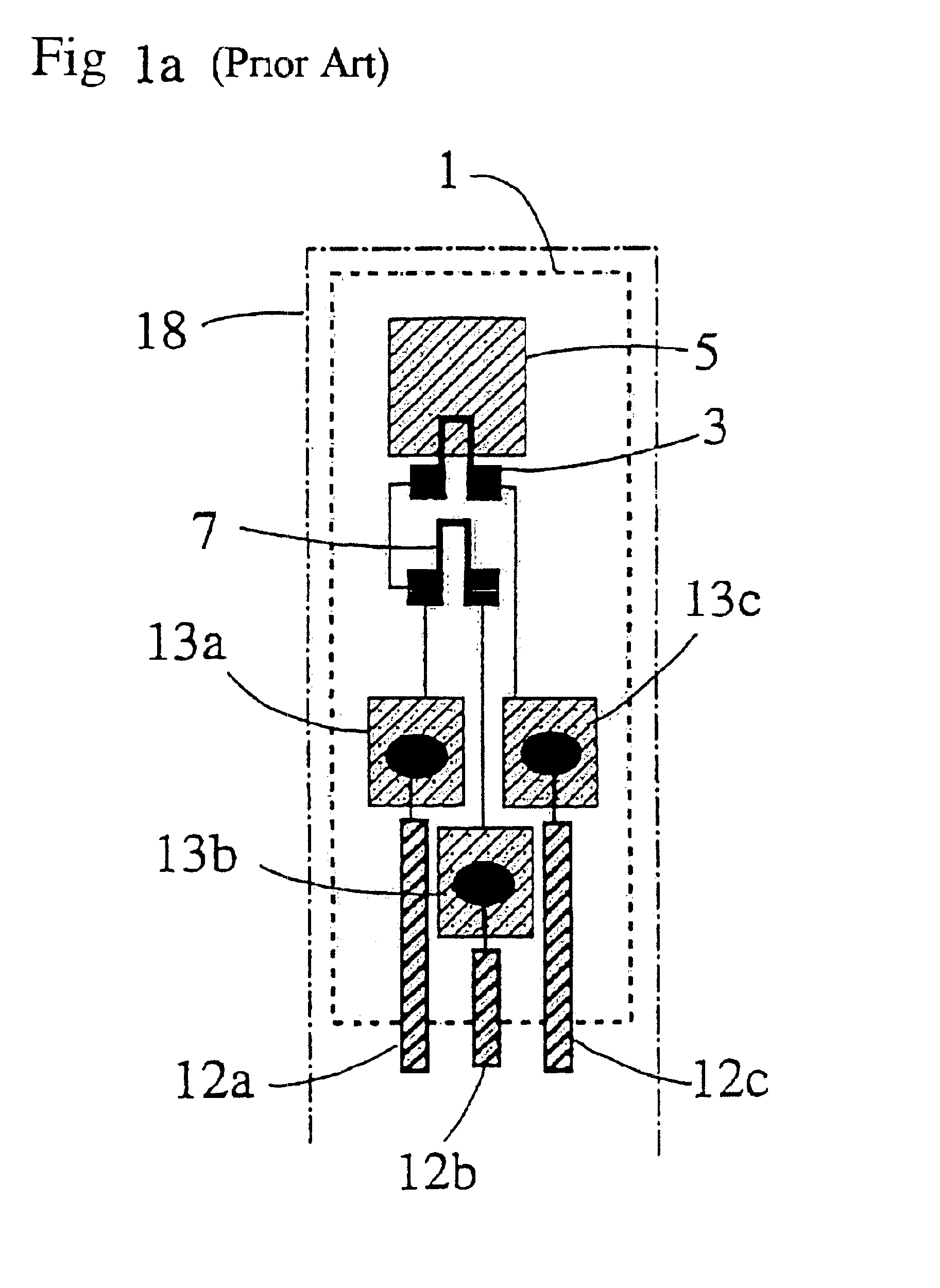
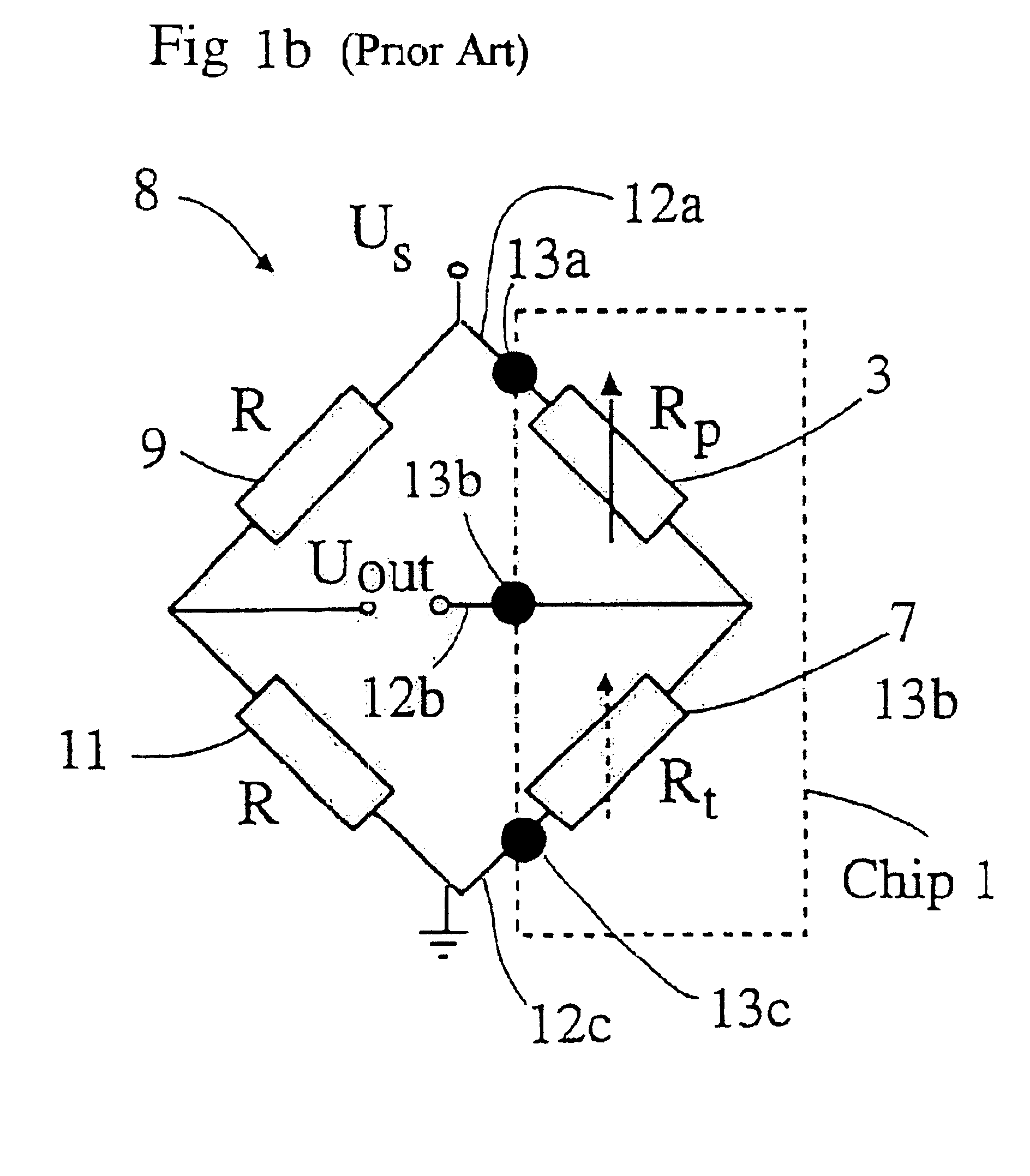
first embodiment
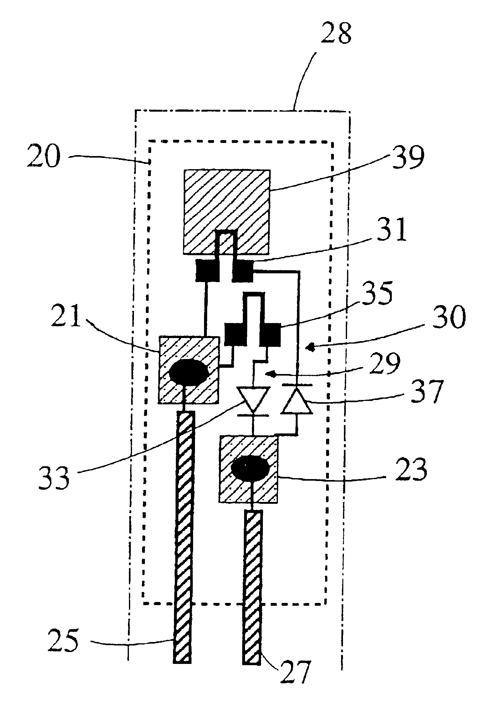
[0039]FIG. 2a is a schematic view of a chip 20 according to the invention. Only two conductors 25 and 27 are connected to the chip 20 through a catheter 28. The chip 20 is adapted to be placed in one end of the catheter 28. This end of the catheter 28 could for example be inserted in a human body. The other end is kept outside the body and is connected to other components in a circuitry for processing the sensed pressure.
[0040]The chip 20 comprises a first terminal pad 21 and a second terminal pad 23. The first conductor 25 is soldered to the first pad 21 and the second conductor 27 is soldered to the second pad 23. The conductors 25,27 are isolated from each other and enclosed in the catheter 28 leading from the chip 20. The pads 21,23 are connected to each other on the chip 20 through two separate parallel branches 29,30. The first branch 29 connects the pads 21,23 through a temperature sensing element, Rt, 35 connected in series with a first diode 33. The second branch 30 connect...
fourth embodiment
[0050]FIG. 3c shows the chip part of a wiring diagram according to the invention. In this embodiment a mechanical switch 45 is used as control means instead of diodes to switch between pressure and temperature measurements. In this embodiment only two branches are shown but it is if needed possible to switch between more than two branches. The branches of the bridge outside the chip comprise only one resistor each of the same type as the resistors on the chip. The switch 45 could be of a kind making a switch from one coupling direction to the other in dependence of the direction of the input voltage to the bridge circuitry and it is manufactured on the chip with micro machining fabrication techniques. The switch 45 could also be of a kind making a switch in dependence of the frequency of an AC supply. Then, the bridge is designed to be operated with and to process at least two kinds of AC supply frequencies.
[0051]In the above described embodiments the pressure and the temperature ha...
fifth embodiment
[0052]FIG. 3d shows the chip part of a wiring diagram according to the invention. Here transistors 51a,51b,51c are used as control means for switching between pressure measurements, temperature measurements and flow rate measurements. The flow rate is measured by a flow rate sensing element 52. The pressure and the temperature is measured as before by a pressure sensing element 31′″ and a temperature sensing element 35′″. Transistors are preferably used for the switching between different parallel branches if there are more than two branches. In this embodiment three parallel branches are shown. The seven resistors in the figure that lack references are provided for producing the needed voltage division to open and close the different transistors. The wiring diagram is easily understood for a person skilled in the art and will not be further described inhere. The wiring diagram could also be varied in a number of ways to give a voltage division needed for opening or closing the tran...
PUM
| Property | Measurement | Unit |
|---|---|---|
| pressure | aaaaa | aaaaa |
| temperature | aaaaa | aaaaa |
| flow rate | aaaaa | aaaaa |
Abstract
Description
Claims
Application Information
 - R&D
- Intellectual Property
- Life Sciences
- Materials
- Tech Scout
- Unparalleled Data Quality
- Higher Quality Content
- 60% Fewer Hallucinations
Browse by: Latest US Patents, China's latest patents, Technical Efficacy Thesaurus, Application Domain, Technology Topic, Popular Technical Reports.
© 2025 PatSnap. All rights reserved.Legal|Privacy policy|Modern Slavery Act Transparency Statement|Sitemap|About US| Contact US: help@patsnap.com