
Plastic pallet

a technology of plastic pallets and pallets, applied in the field of pallets, can solve the problems of splinters, limited strength of wood, and many problems for handlers, and achieve the effect of providing the necessary strength needed for pallet performance, fastening quickly and easily

Inactive Publication Date: 2005-09-06
PERES VICTOR L
View PDF12 Cites 92 Cited by
  • Summary
  • Abstract
  • Description
  • Claims
  • Application Information

AI Technical Summary

Benefits of technology

[0003]As a result, attempts have been made to make plastic pallets. Plastic is a durable material that washes easily and can, if formed properly, provide the necessary strength needed in pallet performance. The components of the plastic pallet of the present invention have been engineered to fasten together quickly and easily and to stay together permanently.

Problems solved by technology

These pallets afford a number of problems for handlers.
First, the wood has limited strength and is subject to breaking.
Even if the boards remain intact, they can create splinters.
However, wood does not wash off well and the exposure of the nails to water produces rust, eventually leading to the pallets coming apart.
Splinters, broken jagged slats, unstable pallets, and rusty nails all contribute to a hazardous work zone for those responsible for manipulating the pallets and their stored goods.
Further, the residual food particles trapped in the interstices of the wood, form breeding grounds for health problems, attract rats and, if nothing else, produce a stench as the food rots.

Method used


Image

  • Plastic pallet
  • Plastic pallet
  • Plastic pallet

Examples


first embodiment

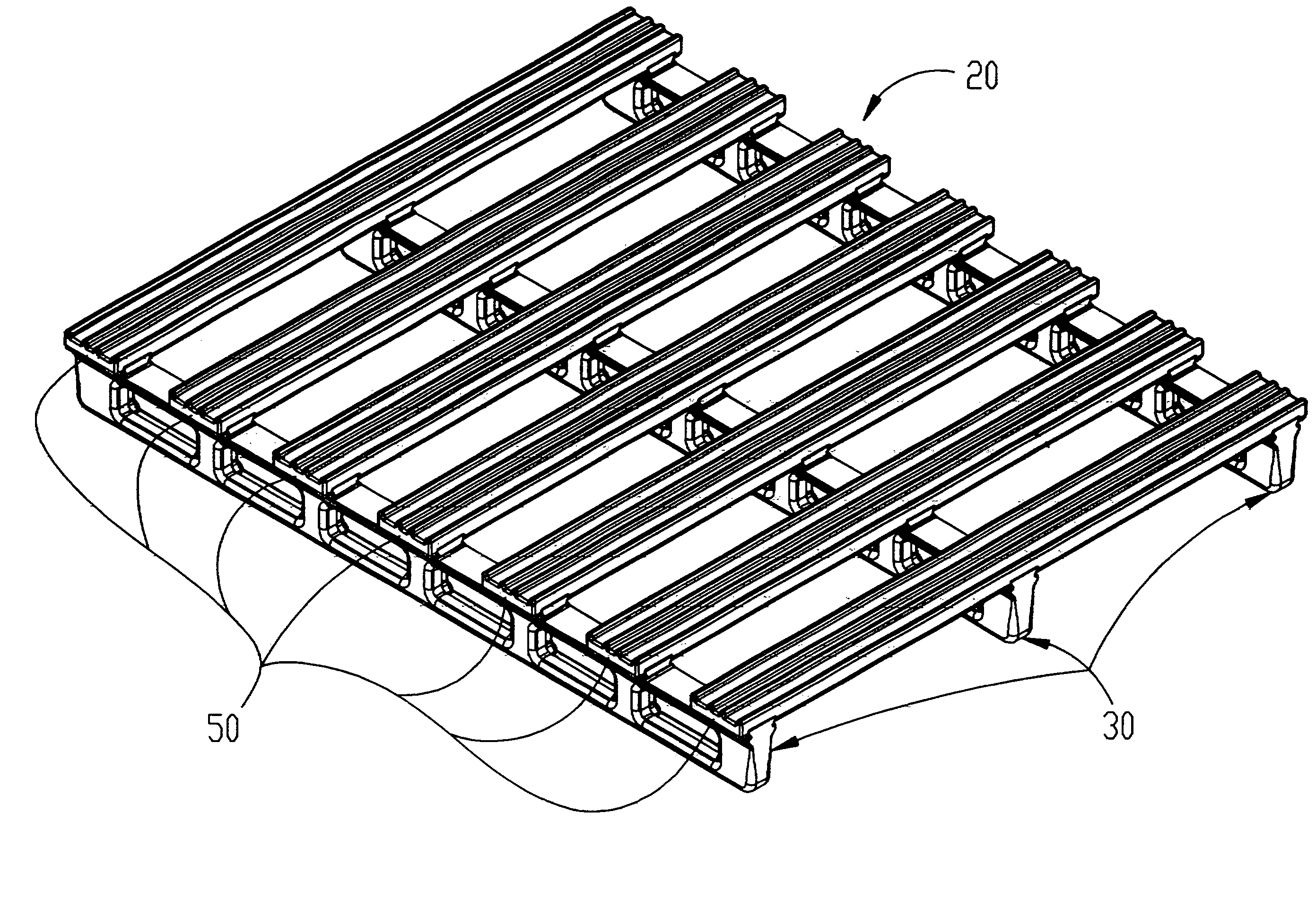
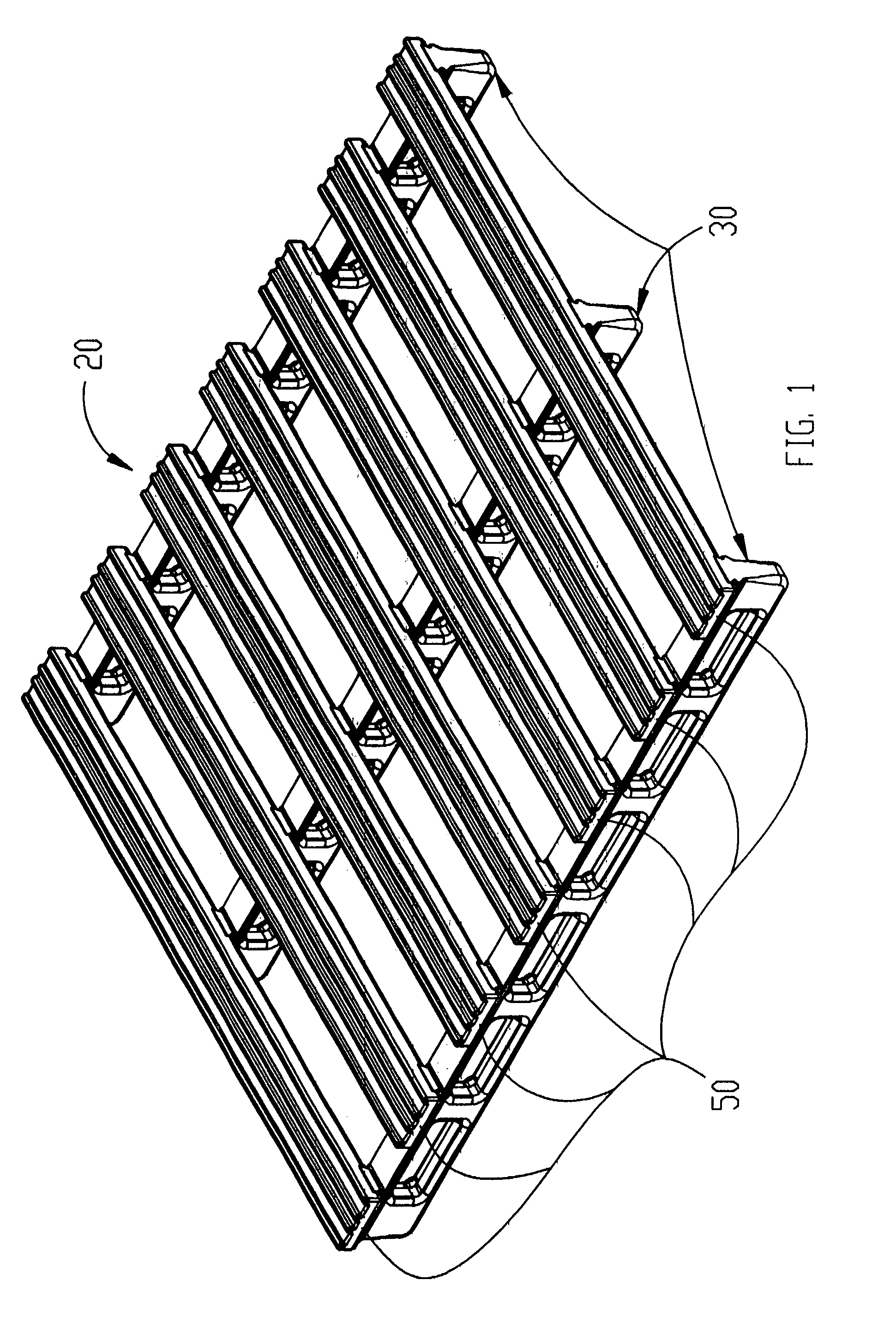
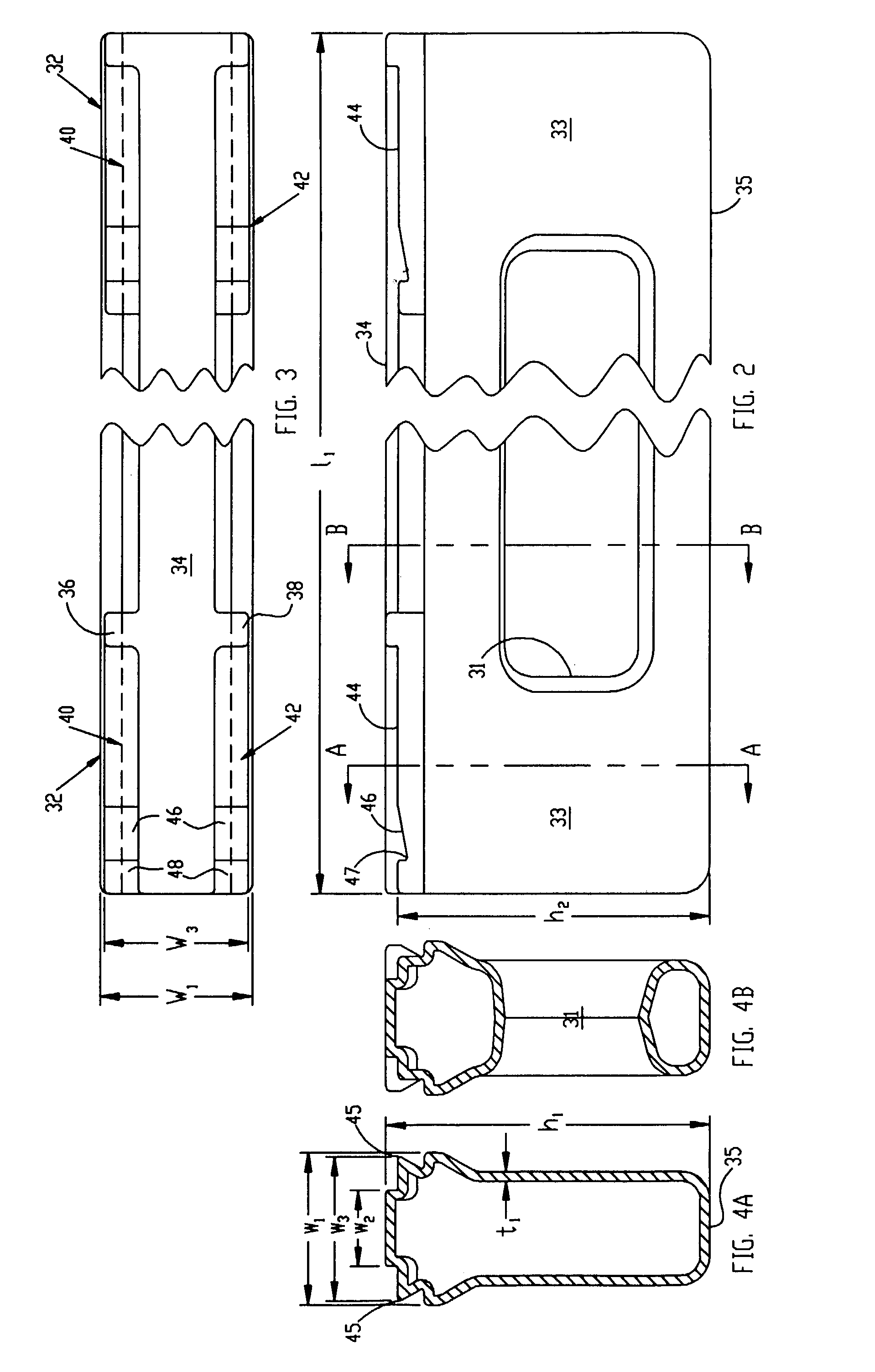
[0021]the plastic pallet of the present invention is shown in FIG. 1 generally at 20. As depicted in that view, plastic pallet 20 is comprised of a first plurality (as depicted in FIG. 1, three) stringers 30 having a first maximum height ha (see FIG. 4A), a first maximum width w1 and an overall length 11, (FIG. 2) extending generally parallel to one another. Supported by and attached to the plurality of stringers 30 at each of a second plurality of attachment regions 32 (FIG. 3) is one of a third plurality of slats 50. Stringers 30 are hollow being formed of polyethylene using a blow molded process and have a generally uniform wall thickness t1, with a plurality of apertures 31 inter-spaced with columns 33 (FIG. 2). Columns 33 provide structural support while apertures 31 reduce the amount of material needed to form the part.

[0022]As seen in more detail in FIGS. 2, 3, 4A, 4B stringer 30 has a first flat, central uppermost surface 34 which has a width w2 which is generally about ½ of...

second embodiment

[0025]plastic pallet of the present invention is shown in FIG. 9 generally at 20′. In this embodiment, the attachment regions 32′ on the top of stringer 30′ is duplicated on the bottom at 32″ (FIGS. 10, 11A, 11B). Typically a fewer number of slats 50″ will be attached to the attachment regions 32″ than slats 50′ attached to regions 32′. These slats will provide increased structural rigidity and, when the pallet 20′ is engaged from the ends (rather than through the holes 31′), these bottom slats will prevent the pallet from falling off the forklift due to tilting of the load as a result of, for example, the operator turning a sharp corner or stopping abruptly such that momentum of the load produces a torquing of the pallet stack.


PUM


Abstract

A two-part, blow-molded plastic pallet includes slats which lock onto support stringers by sliding, dovetail engagement. The upper and lower surfaces of the stringer are flat to enhance load distribution. A vertical staking through the slat at a plurality of locations affords structural rigidity.

Description

BACKGROUND AND SUMMARY OF THE INVENTION[0001]The present invention is directed to the field of pallets for storing / transporting goods. More particularly, the present invention is directed to a plastic pallet with snap together components.[0002]Pallets are typically formed of wood. The components, the stringers and the slats, are held together by nails. These pallets afford a number of problems for handlers. First, the wood has limited strength and is subject to breaking. Even if the boards remain intact, they can create splinters. Further, where pallets are used to store food goods, cleanliness is important. However, wood does not wash off well and the exposure of the nails to water produces rust, eventually leading to the pallets coming apart. Splinters, broken jagged slats, unstable pallets, and rusty nails all contribute to a hazardous work zone for those responsible for manipulating the pallets and their stored goods. Further, the residual food particles trapped in the interstic...

Claims


Application Information

Patent Timeline
IPC IPC(8): B65D19/00
CPCB65D19/0095B65D2519/00034B65D2519/00069B65D2519/00273B65D2519/00293B65D2519/00298B65D2519/00323B65D2519/00333B65D2519/00373B65D2519/00407B65D2519/00412B65D2519/00557B65D2519/00562B65D2519/00567B65D2519/00835B65D2519/0098Y10S108/901
Inventor PERES, VICTOR L
Owner PERES VICTOR L
Learn More