Methods for controlling screenouts

Inactive Publication Date: 2005-09-06
SCHLUMBERGER TECH CORP
View PDF31 Cites 116 Cited by
  • Summary
  • Abstract
  • Description
  • Claims
  • Application Information

AI Technical Summary

Benefits of technology

[0014]One embodiment of the Invention is a method of causing a screenout, during stimulation of a subterranean formation by propped fracturing, by forming a filter cake and then degrading the filter cake with a filter cake degradation agent while injecting proppant slurry into the fracture. In some embodiments the filter cake is formed from the viscosifier for the carrier fluid in the slurry or from a fluid loss additive or both. In some embodiments the filter cake degradation agent may be an oxidizer, an enzyme, an acid or mixtures of these. Another embodiment is a method of causing a screenout in a subterranean formation stimulation treatment, including injecting a slurry of a proppant in a carrier fluid above fracturing pressure to create one or more fractures, the method including the steps of injecting a pad fluid that forms a filter cake; injecting one or more first slurry stages comprising a proppant in a carrier fluid; and degrading the filter cake with a filter cake degradation agent while injecting one or more second slurry stages comprising a proppant in a carrier fluid. In other embodiments of this method, the pad fluid includes one or more than one of fluid loss additives, filter cake degradation agents, filter cake degradation agent aids, and mixtures thereof, provided that no filter cake degradation agent aid is included for a filter cake degradation agent that is included; the one or more first slurry stages include one or more than one of fluid loss additives, filter cake degradation agents, filter cake degradation agent aids, and mixtures thereof, provided that no filter cake degradation agent aid is included for a filter cake degradation agent that is included or was in the pad; and the one or more second slurry stages include one or more than one of filter cake degradation agents, filter cake degradation agent aids, and mixtures thereof. In another embodiment, the pad fluid and the one or more first slurry stages each include a fluid loss additive, a first filter cake degradation agent and a filter cake degradation agent aid for a second filter cake degradation agent that is more active under t

Problems solved by technology

High permeability formations are frequently poorly consolidated, so that sand control is needed.
It is very undesirable to allow the proppant or gravel to pack the wellbore above the producing formation.
It is also very undesirable if the operation screens out too late or not at all, that is if the fracture keeps growing, in length and/or in height, beyond what is necessary and desired, and an optimal pack and desired fracture size and shape are never generated to maximize production and to prevent flowback of proppant or sand.
In a tip screenout, the solids concentration at the tip of the fracture becomes so high due to fluid leak-off into the formation that the slurry is no longer mobile.
This filter cake reduces the flow of fluid from the fracture into the formation (affecting the “efficiency” of the job (see below)).
If a tip screenout is encountered in such a fracturing operation before the entire designed treatment is pumped, as inferred from an increase in pumping pressure, the pump rate is reduced or most likely the treatment is stopped and considered a failure.
Unfortunately, in spite of

Method used


Image

  • Methods for controlling screenouts
  • Methods for controlling screenouts
  • Methods for controlling screenouts

Examples


example 1

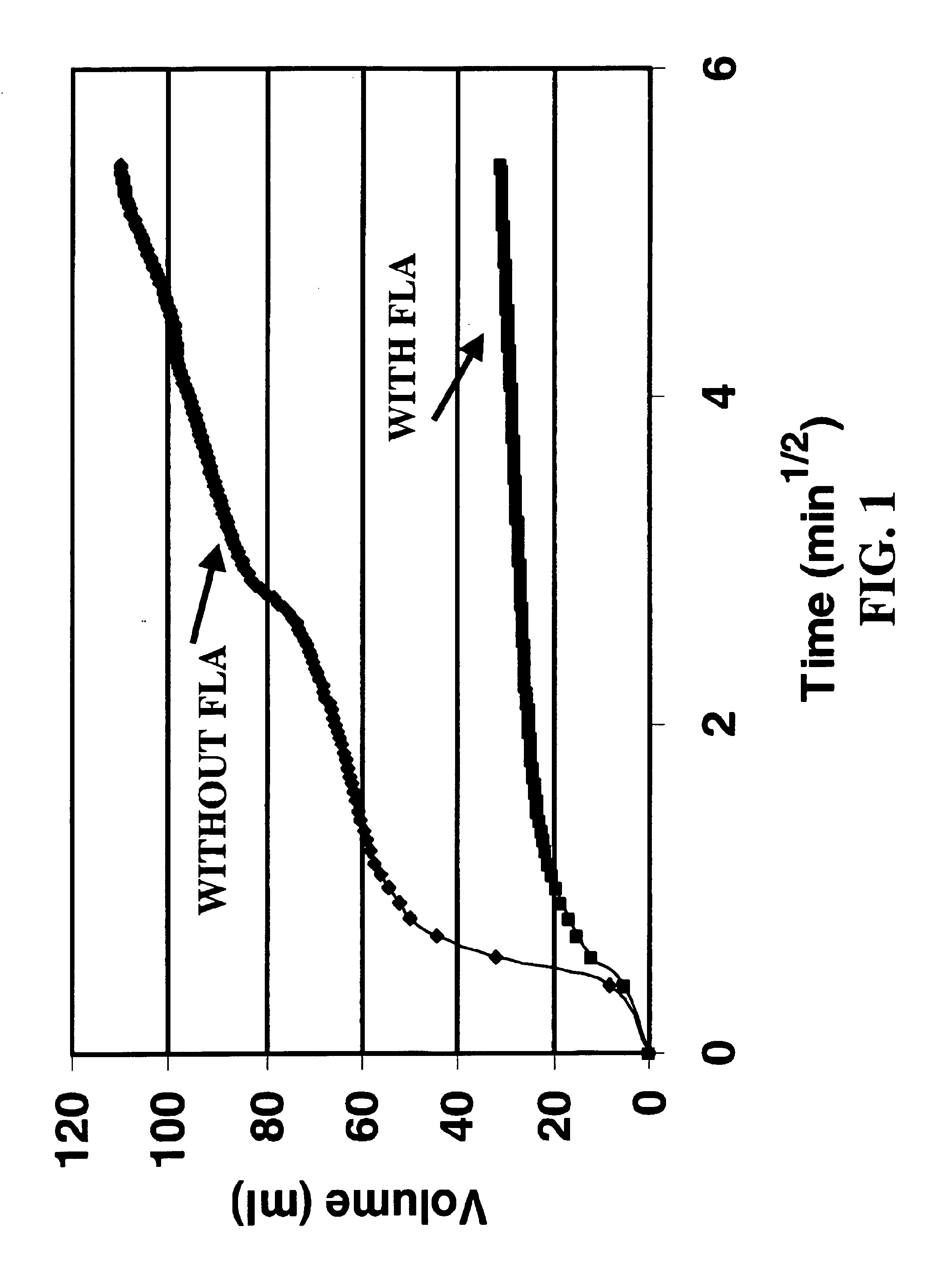
[0057]1.5 in. diameter cores were saturated in a test brine (2 gallons per thousand gallons of a 50 per cent solution of tetra methyl ammonium chloride) prior to dynamic fluid loss tests. The dynamic fluid loss apparatus consists of a core holder designed so that fluids can be flowed across one end face of the core (the front end) in such a way that some of the fluid will leak off into the core, and fluids can be injected into the other end (the back end) of the core to measure core permeability; the system is controlled by automation software. Brine was injected into the back end of the core to measure the initial permeability. Dynamic fluid loss was performed by flowing a borate crosslinked guar fluid (at a 20 lb. guar / 1000 gallons of fracturing fluid concentration) across the face of the core for 30 minutes at a differential pressure of about 500 psi. (This results in some flow of fluid into the core, and formation of a filter cake on the core face if there is a filter cake formi...

example 2

[0061]FIG. 3 shows laboratory experiments demonstrating a method of the Invention using two FLA breaker (filter cake degradation agent) stages. These are dynamic fluid loss test runs at 52° C. by the same method as Example 1. It can be seen that in test one when the first half contained an FLA and a first breaker and a breaker aid (filter cake degradation agent aid) for a second breaker that was present in the second half, and there was still FLA in the second half, there was no increase in fluid loss in the second half. In test two, when the first half was like the first half of test one but the second half contained no FLA, there was a dramatic increase in the volume of fluid lost in the second half, indicating that the filter cake had been severely damaged. In a fracture, this would translate into bridging and / or reduced fluid efficiency and a TSO. To ensure that the result was not due solely to the exclusion of the FLA from the second half of test 2, another laboratory test was ...

example 3

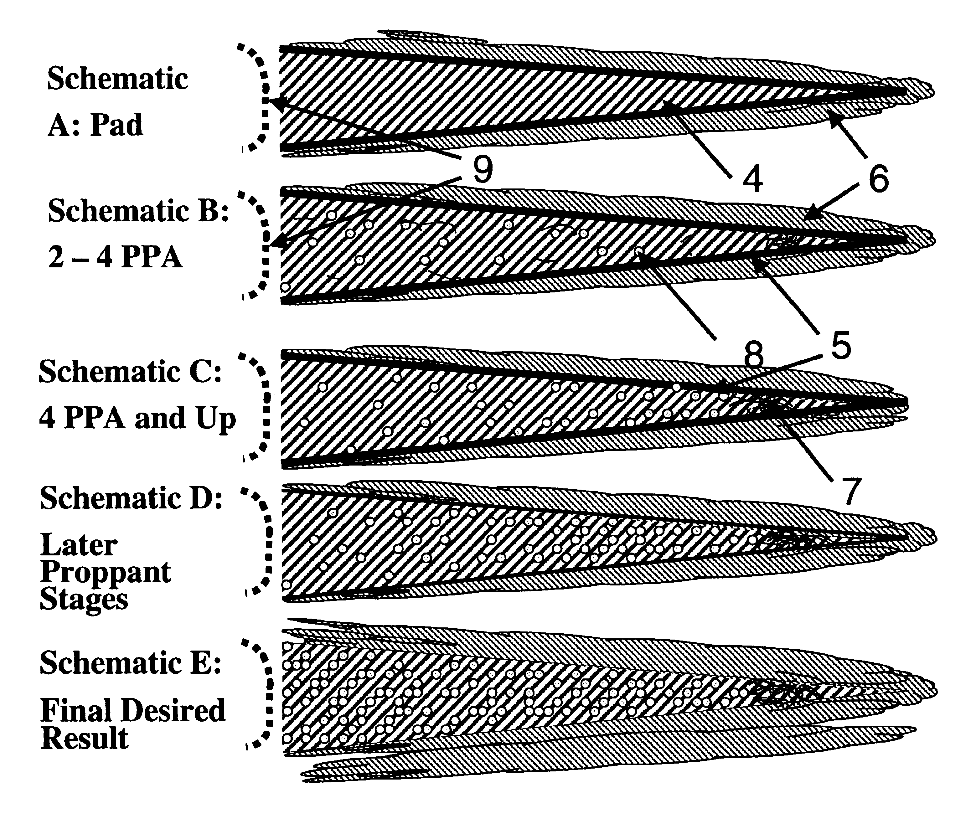
[0062]FIG. 5 demonstrates the effect of adding fiber to promote bridging in addition to adding an FLA and breakers. The figure shows a particular embodiment in which a filter cake with a built-in breaker is created with the pad, then fibers are added to the proppant stage to promote bridging, and then another breaker is added to the later proppant stages. (Schematics A through E of the contents of the fracture are shown from top to bottom as the stimulation progresses; these could be either top views or side views and are not to scale and the fractures are not necessarily the same size in successive schematics.) This sequence stops the fracture growth and then removes the filter cake, which ultimately increases the flow rate, into the fracture, of the fluid to be produced. The viscosifier in the pad, the first filter cake degradation agent, the filter cake degradation agent aid for the second filter cake degradation agent, and the FLA are the same as those in the first half of test ...


PUM


Abstract

Methods are presented to induce a screenout during a subterranean formation fracturing or combined fracturing and gravel packing treatment by laying down a filter cake early in the treatment, then injecting proppant slurry, and then while proppant slurry injection continues chemically damaging the filter cake with one or more filter cake degradation agents so that leak-off increases, the concentration of proppant in the fracture increases, and the proppant screens out. The additional use of filter cake degradation agent aids and bridging-promoting materials is included.

Description

REFERENCE TO RELATED PROVISIONAL APPLICATION[0001]This application claims the benefit of provisional application No. 60 / 334,703 filed Oct. 31, 2001.TECHNICAL FIELD OF THE INVENTION[0002]This Invention relates to increasing the flow of fluids into or out of subterranean wells. More particularly it relates to stimulation of the flow of fluids from the rock of a formation into a wellbore. Most particularly it relates to methods of controlling the size and shape, location, and quality of fractures created in hydraulic fracturing (either conventional or with coiled tubing), or in fracturing and gravel packing in one operation, or in gravel packing.BACKGROUND OF THE INVENTION[0003]Hydraulic fracturing, gravel packing, or fracturing and gravel packing in one operation, are used extensively to stimulate the production of hydrocarbons, water and other fluids from subterranean formations. These operations involve pumping a slurry of “proppant” in hydraulic fracturing (natural or synthetic mat...

Claims


Application Information

Patent Timeline
IPC IPC(8): C09K8/60C09K8/74C09K8/70C09K8/62
CPCC09K8/62C09K8/703C09K8/74Y10S507/924
Inventor BONEY, CURTIS L.MILLER, MATTHEW J.
Owner SCHLUMBERGER TECH CORP
Why Eureka
Try Eureka