Steering apparatus and method for automotive vehicle

a technology for steering apparatus and automotive vehicles, applied in steering initiations, vessel parts, instruments, etc., can solve the problem of increasing manufacturing costs and achieving the effect of low cost effectiveness

Inactive Publication Date: 2005-09-06
NISSAN MOTOR CO LTD
View PDF15 Cites 28 Cited by
  • Summary
  • Abstract
  • Description
  • Claims
  • Application Information

AI Technical Summary

Benefits of technology

[0006]It is, therefore, an object of the present invention to provide steering apparatus and method for an automotive vehicle which are capable of providing an optimum assistance torque during the connection of the clutch, according to an estimation of the steering torque using an steering angle sensor and a turning angle sensor which are already installed in a system although the system is a low cost effectiveness and a space saving without installation of the torque sensor installed in proximity to the steering input section.

Problems solved by technology

Hence, a manufacturing cost is accordingly increased due to the presence of the torque sensor.

Method used


Image

  • Steering apparatus and method for automotive vehicle
  • Steering apparatus and method for automotive vehicle
  • Steering apparatus and method for automotive vehicle

Examples


first embodiment

(First Embodiment)

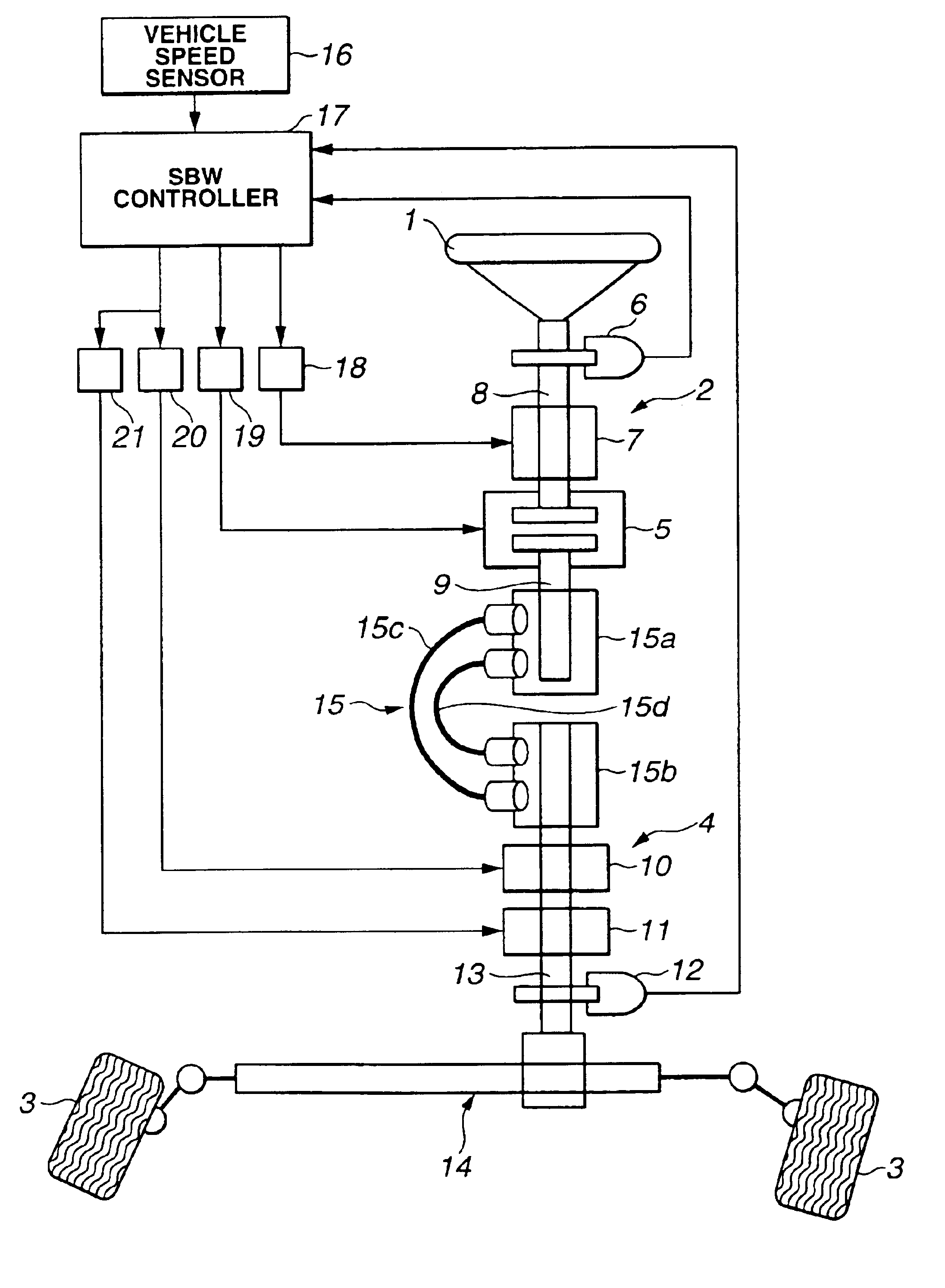
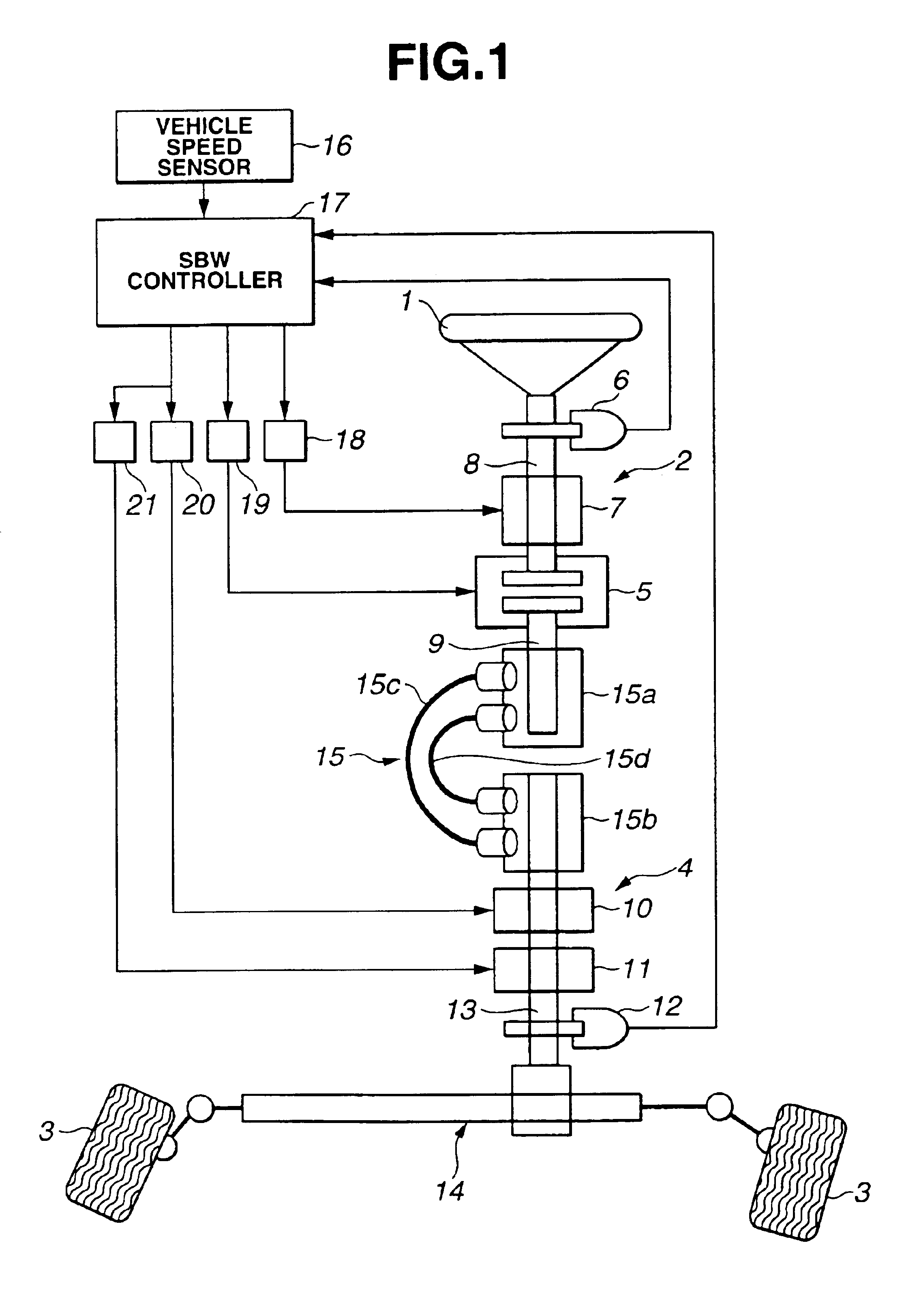
[0015]FIG. 1 shows a whole system configuration view of a vehicular steering apparatus in a preferred embodiment according to the present invention. In the first embodiment, a tuning actuator of a steer-by-wire system (hereinafter also referred to as a SBW system) is a duplex system for a fail safe purpose is exemplified.

[0016]In FIG. 1, a steering wheel (a steering input section) 1 is installed within a vehicular passenger compartment (not shown). A reference numeral 2 denotes an operation portion. A reference numeral 3 denotes steered road wheels and a reference numeral 4 denotes a turning section. A reference numeral 5 denotes a clutch. A reference numeral 6 denotes a steering angle sensor. A reference numeral 7 denotes a reaction force actuator. A reference numeral 8 denotes steering angle sensor. A reference numeral9 denotes a second column shaft (steering axle). A reference numeral 10 denotes a fist turning (angle) actuator. A reference numeral 11 denotes a s...

second embodiment

(Second Embodiment)

[0046]A second preferred embodiment of the steering apparatus is an example of a combination of SWB system (reaction force actuator+turning actuator) with a hydraulic power steering system (hereinafter, referred to as a hydraulic PS system). The structure of the second embodiment will be described with reference to FIG. 3. In FIG. 3, reference numeral 1 denotes steering wheel (operation input section), reference numeral 2 denotes operation portion, reference numeral 3 denotes each steered road wheel, reference numeral 4 denotes turning section, reference numeral 5 denotes a clutch, reference numeral 6 denotes steering angle sensor 9, reference numeral 7 denotes reaction force actuator, reference numeral 8 denotes first column shaft (steering axle), reference numeral 9 denotes second column shaft (steering axle), reference numeral 10 denotes a turning actuator, reference numeral 12 denotes a pinion angle sensor (turning angle sensor), reference numeral 13 denotes p...


PUM


Abstract

In steering apparatus and method for an automotive vehicle, a turning section that turns steered road wheels is provided, a clutch is installed in a predetermined position in a midway through a steering system from an operation input section to the steered road wheels to link between the operation input section and the steered road wheels, a steering angle of the operation portion is detected, a turning angle is detected, an elastically deformable member is interposed between the operation portion and the turning portion to transmit a steering torque inputted from the operation input section to the steered road wheels when the clutch causes the operation input portion and the steered road wheels to be connected; and an angular deviation between the steering angle detection value and the turning angle detection value developed due to a deformation of the member is calculated.

Description

BACKGROUND OF THE INVENTION[0001]1. Field of the Invention[0002]The present invention relates to a technique of, so-called, steer-by-wire type steering apparatus and method for an automotive vehicle in which a clutch to link an steering input section to steered road wheels which are mechanically separated is interposed in a midway through a steering system from the steering input section to the steered road wheels.[0003]2. Description of the Related Art[0004]A Japanese Patent Application First Publication No. 2002-145098 published on May 22, 2002 (which corresponds to a U.S. Pat. No. 6,442,462 issued on Apr. 27, 2002) exemplifies a previously proposed steering system of the steer-by-wire type. In the previously proposed steering system disclosed in the above-described Japanese Patent Application First Publication, a torque sensor is interposed between a steering wheel and a reaction motor. In a case where part of a system fails, the clutch is connected so that a steering force with ...

Claims


Application Information

Patent Timeline
Patent Type & Authority Patents(United States)
IPC IPC(8): B62D5/00B62D6/10B62D6/08B62D1/16B62D6/00B62D5/04B62D101/00B62D113/00
CPCB62D1/163B62D5/003B62D6/10B60Y2400/301
Inventor ONO, HITOSHIHARA, KAZUOSHITAMITSU, KIYOTAKAEGUCHI, TAKAAKIKATOU, YUUSUKEKASAHARA, TOSHIAKI
Owner NISSAN MOTOR CO LTD
Why Eureka
Try Eureka