Integrated engine compartment component and air intake system

Active Publication Date: 2005-09-06
SIEMENS VDO AUTOMOTIVE CORP
View PDF11 Cites 12 Cited by
  • Summary
  • Abstract
  • Description
  • Claims
  • Application Information

AI Technical Summary

Benefits of technology

[0008]Accordingly, the above invention provides a way of incorporating a noise cancellation system, such as an

Problems solved by technology

Various passive or active noise cancellation systems may be connected to the air intake and are located within the engine compartment, which because of their size may be difficult to package within the tight confines of modern engine compartments.
Furthermore, increasing demands have been placed

Method used


Image

  • Integrated engine compartment component and air intake system
  • Integrated engine compartment component and air intake system
  • Integrated engine compartment component and air intake system

Examples


Example

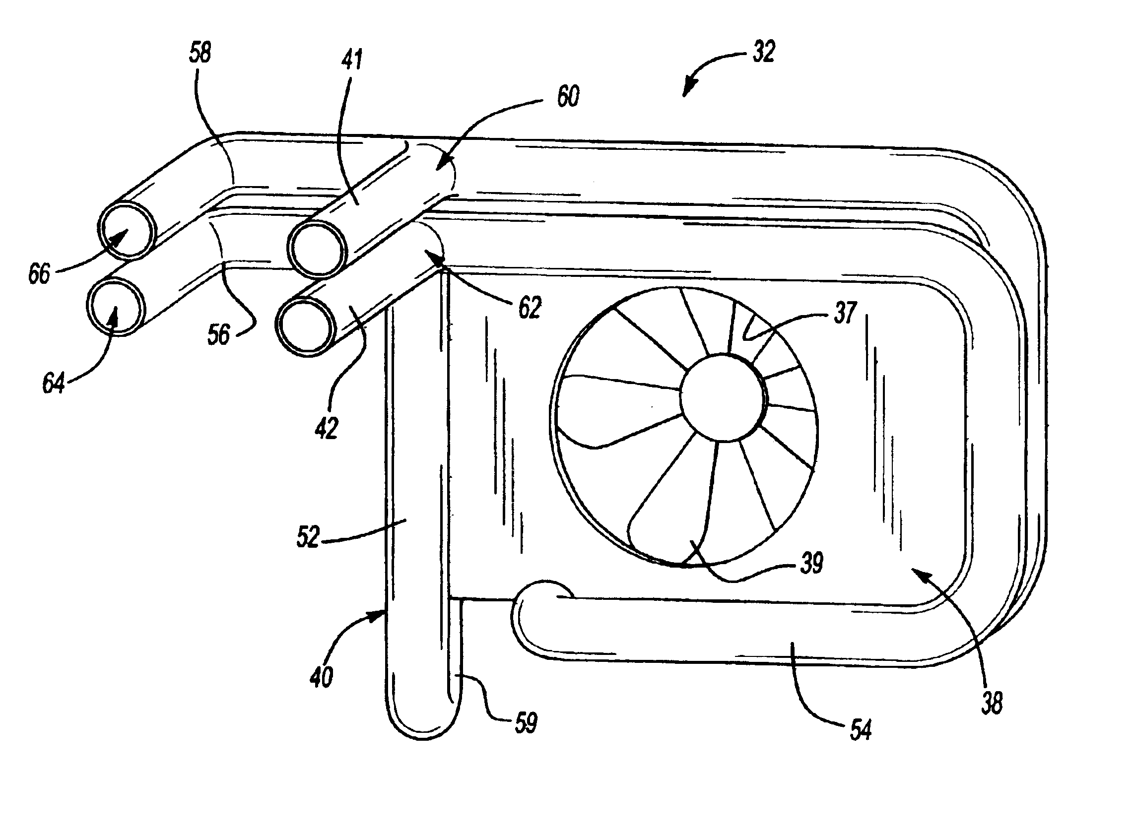
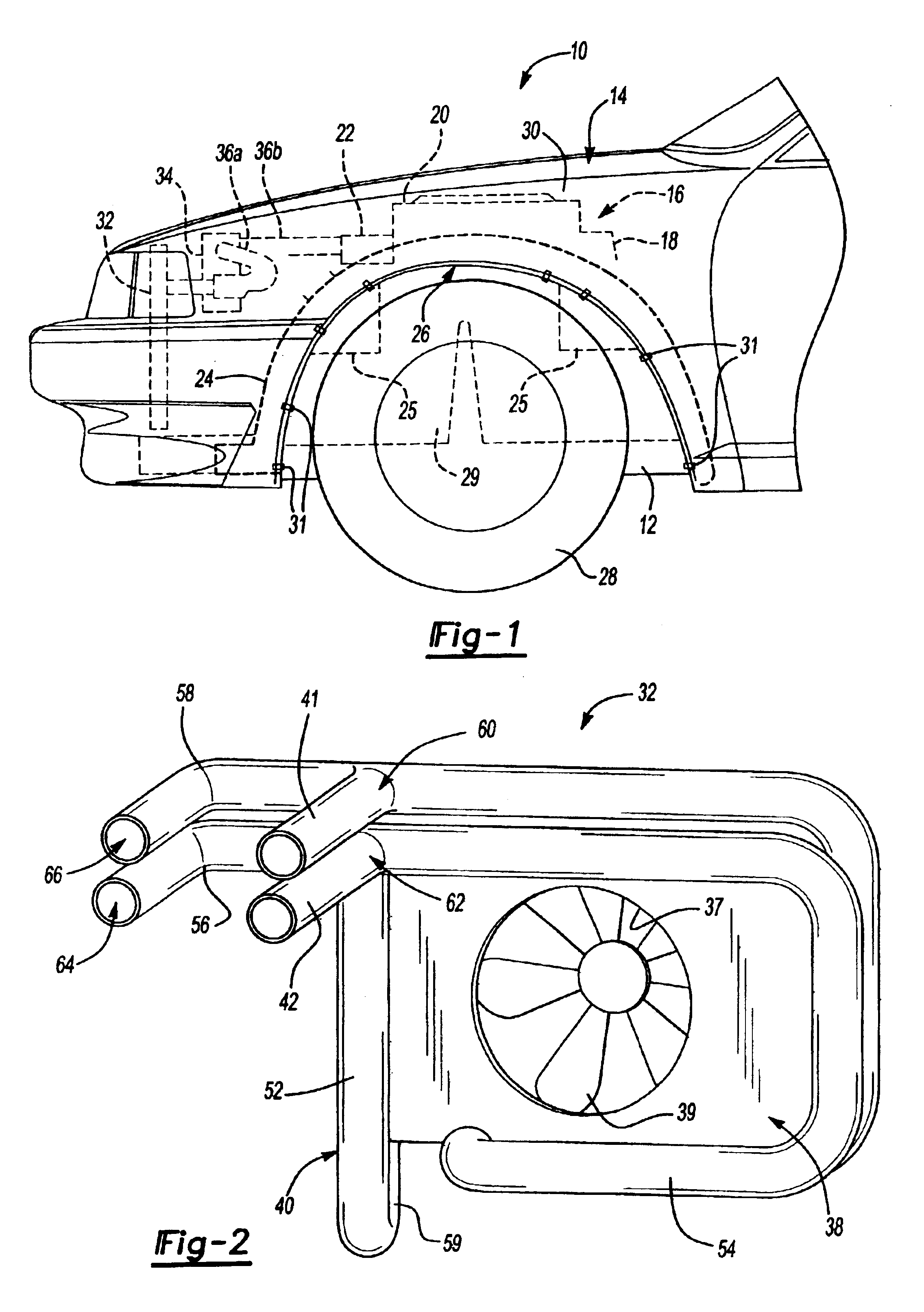
[0015]A vehicle 10 incorporating the present invention integrated splash shield and air intake tube is shown in FIG. 1. The vehicle 10 includes a frame 12 and a body 14 supported on the frame 12. The frame 12 and body 14 together define an engine compartment 16 at the forward end of the vehicle 10. However, it is to be understood that the present invention may be utilized in a different location, for example, at the rear of the vehicle for rear engine configurations. The vehicle 10 includes an engine 18 having an intake manifold 20 and throttle 22 disposed within the engine compartment 16, as is well known in the art. An air cleaner box 34 may be connected between the present invention fan shroud 32 and the throttle 22 of the engine 18 by tubing 36a and 36b.

[0016]A splash shield 24 is arranged between the engine compartment 16 and a body fender 30 to define a wheel well 26. The splash shield 24 is C-shaped and arranged at least partially around a wheel 28 to prevent water and debri...


PUM


Abstract

A fan shroud includes a fan shroud portion having a surface including an aperture. A cooling fan is supported proximate to the aperture for permitting air flow through the fan shroud from the environment to the engine compartment. An air intake portion is supported on the fan shroud portion. The air intake portion and the fan shroud portion together define at least a portion of an air passageway having an inlet for receiving ambient air and an outlet for connection to an engine throttle. The fan shroud portion and air intake portion may respectively include first and second circumferential portions that define the air passageway.

Description

RELATED APPLICATIONS[0001]This application claims priority to U.S. Provisional Application No. 60 / 385,378, filed on Jun. 3, 2002.BACKGROUND OF THE INVENTION[0002]This invention relates to a splash shield and an air intake system, and more particularly, the invention relates to an integrated air intake system and / or fan shroud and / or splash shield, which may incorporate noise cancellation ductwork. Splash shields are typically simple C-shaped plastic structures arranged in each wheel well above the wheels to prevent water and debris from entering the engine compartment. For vehicles having forward located engine compartments, fan shrouds are arranged proximate to the grill. The fan shroud includes an aperture, and a cooling fan is supported proximate to the aperture for cooling the engine.[0003]Vehicle air intake systems route air from the environment to the engine for use in the combustion process. Air intake systems include a tube with an opening, typically located at the front of ...

Claims


Application Information

Patent Timeline
IPC IPC(8): F02M35/10F02M35/12B60K11/04B60K13/02F02M35/16
CPCB60K11/04B60K13/02F02M35/10013F02M35/10144F02M35/10288F02M35/161F02M35/1261F02M35/1266F02M35/1288
Inventor XIA, ZHOUXUAN
Owner SIEMENS VDO AUTOMOTIVE CORP
Why Eureka
Try Eureka