
MEMS Transducer for an Audio Device

a technology of microelectromechanical system and audio device, which is applied in the direction of electrical transducers, mics, electrical equipment, etc., can solve the problems of unfavorable electrical output signal noise, unfavorable sound quality, and unfavorable sound quality, and achieve the effect of facilitating the manufacturing process and easy manufacturing process of the mems transducer

Inactive Publication Date: 2012-03-08
KNOWLES ELECTRONICS ASIA
View PDF0 Cites 12 Cited by
  • Summary
  • Abstract
  • Description
  • Claims
  • Application Information

AI Technical Summary

Benefits of technology

[0017]Further, the MEMS transducer may be versatilely used in various electrical devices, since its shows an excellent performance in terms of usefulness for the measurement of small signals as the body noise due to movements of the transducer may be totally cancelled out.
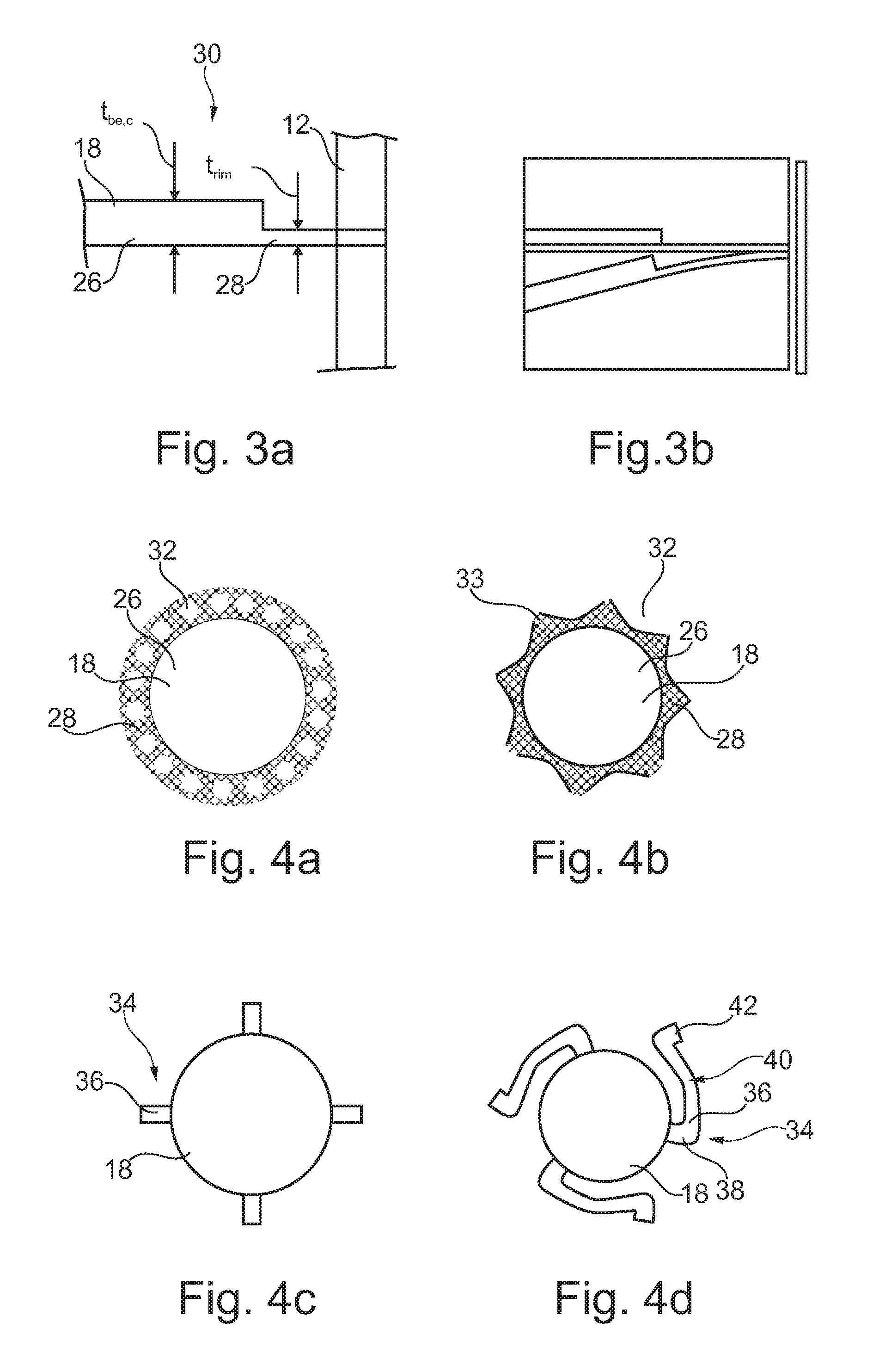
[0034]These configurations of the suspension may allow a motion of the back-electrode in three degrees of freedom. In particular, the spring arms may allow for rotational movement of the back-electrode upon mechanical vibrations. In particular, the spring arms may be designed spiral-like, tangentially extending from the back-electrode and interconnecting the back-electrode and the substrate. In particular, the spring arms may be arranged at opposed positions along the circumference of the back-electrode, whereby a mechanical stable connection between the substrate and the back-electrode is guaranteed. According to an exemplary embodiment of the MEMS transducer, a difference in the resonant frequency of the membrane and the resonant frequency of the back-electrode is less than 20%, preferably less than 5%, further preferably less than 1%. This measure allows a low level of body-noise. A higher degree of frequency matching may allow a better body noise suppression. For instance, in case the difference in the resonant frequencies of membrane and the back-electrode is less than 20%, a 10 dB improvement in noise suppression may be achieved. Matching the resonant frequency of the back-electrode within 5% to the resonant frequency of the membrane, body noise of approximately 20 dB may be cancelled out. A higher degree of frequency matching may yield a further improved body noise cancellation.

Problems solved by technology

However, the known microphone does not only respond to sound pressure waves, as described above, but also to movement of the body of the microphone.
This undesired effect is called body noise and is caused by movement of the membrane and / or back-electrode in response to movement of the whole body.
Thus, the noise level of the electrical output signal is increased considerably, making the MEMS transducer unsuitable for measurement of very small input signals.

Method used


Image

  • MEMS Transducer for an Audio Device
  • MEMS Transducer for an Audio Device
  • MEMS Transducer for an Audio Device

Examples


Embodiment Construction

[0046]The illustration in the drawing is schematically. In different drawings, similar or identical elements are provided with similar or identical reference signs.

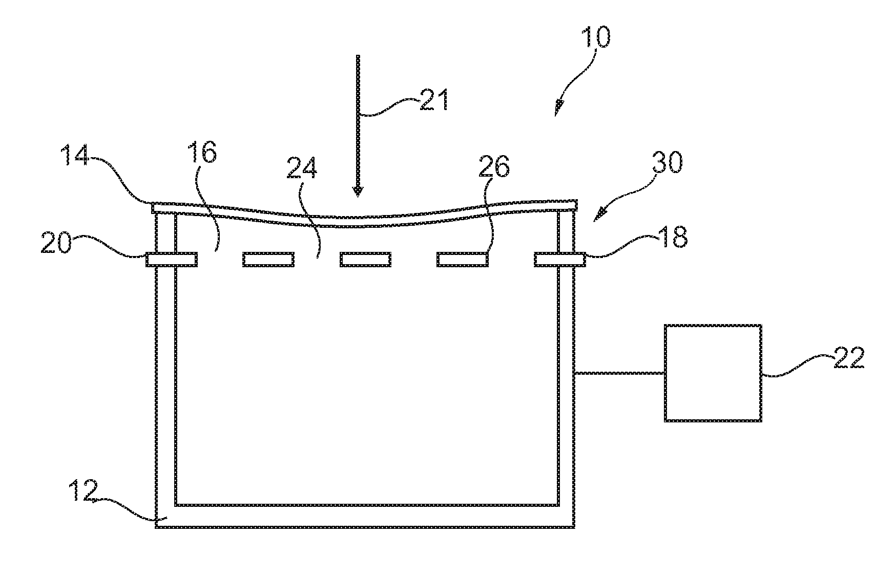
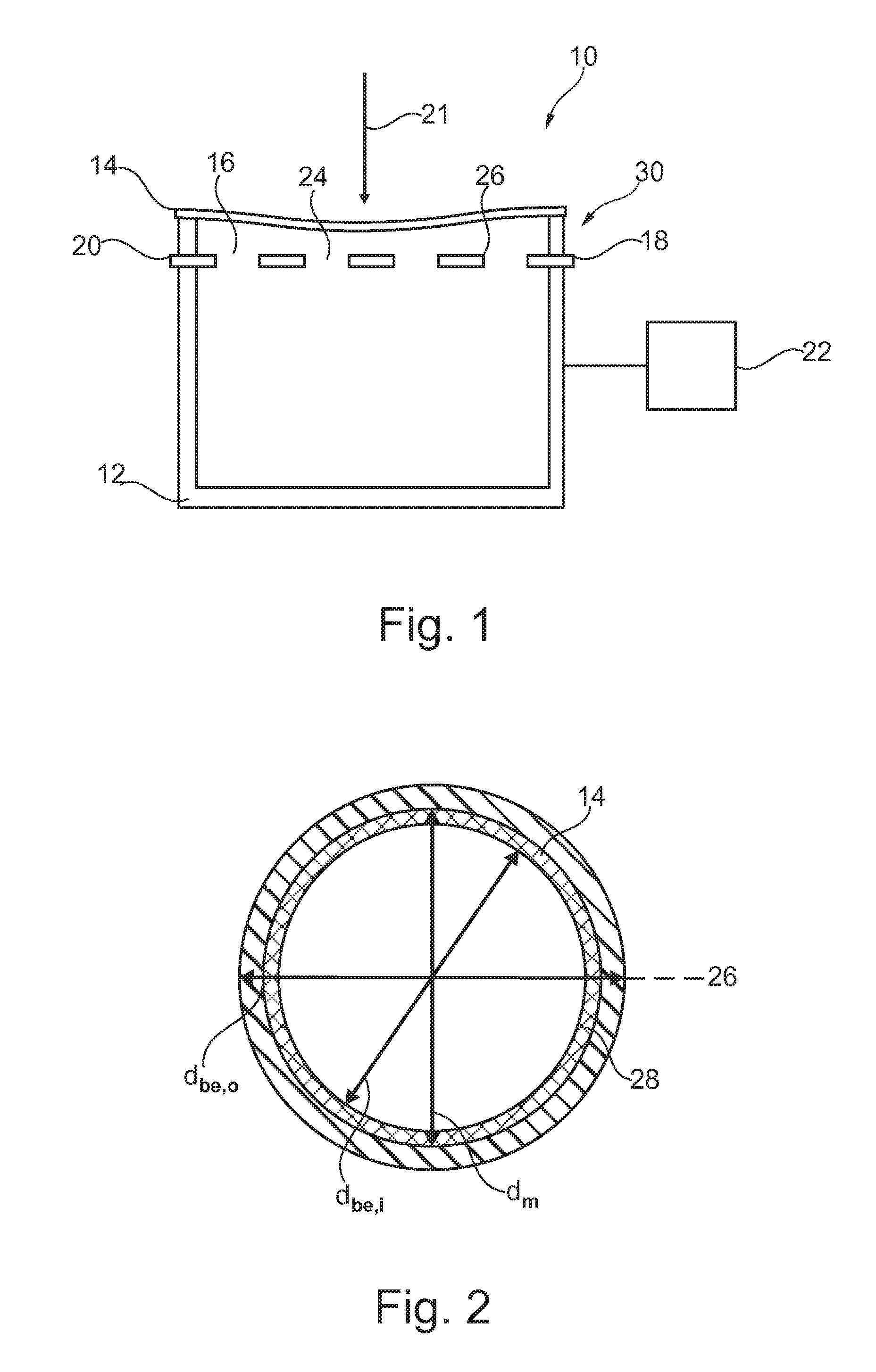
[0047]FIG. 1 schematically shows a cross-sectional side view of a MEMS microphone 10 according to the invention. The MEMS microphone 10 is of capacitor type and may be part of a mobile phone. The MEMS microphone 10 has low body noise due to mechanical vibrations of its elements, in particular its membrane and its back-electrode, since the back-electrode is designed to have a synchronous mechanical response on mechanical vibration of the whole microphone 10.

[0048]The MEMS microphone 10 comprises a cylindrical back-chamber 12 which serves as a resonator of the MEMS microphone 10. Further, a membrane 14 or diaphragm covers an opening 16 of the back-chamber 12. The membrane 14 is fixed to a circumference of the back-chamber 16. A back-electrode 18 is arranged within the back-chamber 12 next to the membrane 14 in such a way th...


PUM

PropertyMeasurementUnit
Fractionaaaaaaaaaa
Fractionaaaaaaaaaa
Fractionaaaaaaaaaa

Abstract

A MEMS transducer (10) for an audio device comprises a substrate (12), a membrane (14) attached to the substrate (12), and a back-electrode (18) attached to the substrate (12), wherein a resonant frequency of the back-electrode (18) is matched to a resonant frequency of the membrane (14). Further, a method of manufacturing a MEMS transducer (19) for an audio device comprises attaching a membrane to a substrate (12), attaching a back-electrode (18) to the substrate (12), matching a resonant frequency of the back-electrode (18) to a resonant frequency of the membrane (14).

Description

FIELD OF THE INVENTION[0001]The invention refers to a microelectromechanical system (MEMS) transducer for an audio device.[0002]Further, the invention relates to a method of manufacturing a MEMS transducer for an audio device.BACKGROUND OF THE INVENTION[0003]MEMS transducers may be designed as microphones used in mobile phones to convert a sound signal to an electrical output signal.[0004]U.S. Pat. No. 6,812,620 B2 discloses a microphone of capacitor type which comprises an acoustically closed microphone back-chamber to which a rigid back-electrode and a membrane are fixed. The membrane covers the microphone back-chamber, and the back-electrode is arranged next to the membrane in a parallel way such that a small air gap is left between both the membrane and the back-electrode. The membrane and the back-electrode comprise conductive layers which form a capacitor. Further, the back-electrode comprises holes allowing for pressure release into the microphone back-chamber, whereby the ba...

Claims


Application Information

Patent Timeline
IPC IPC(8): H01L29/84H04R31/00
CPCH04R19/00Y10T29/49005H04R2499/11
Inventor VAN LIPPEN, TWANLANGEREIS, GEERTLUTZ, JOSEFSUY, HILCOVAN DER AVOORT, CASJANSMAN, ANDREAS BERNARDUS MARIA
Owner KNOWLES ELECTRONICS ASIA
Learn More