Method and an assembly for braking a selectively moveable assembly having a controllably varying amount of self energization

a selectively movable assembly and self-energizing technology, which is applied in the direction of braking systems, braking components, transportation and packaging, etc., can solve the problems of increasing the overall cost of producing the vehicle, undesirably increasing the overall production cost of the vehicle or other selectively movable assembly, and undesirable architectur

Inactive Publication Date: 2005-09-06
FORD GLOBAL TECH LLC
View PDF13 Cites 14 Cited by
  • Summary
  • Abstract
  • Description
  • Claims
  • Application Information

AI Technical Summary

Benefits of technology

[0017]It is a second non-limiting advantage of the present invention to provide a method for braking a selectively movable assembly which overcomes some or all of the drawbacks associated with prior braking methods.
[0018]It is a third non-limiting advantage of the present invention to provide an electromechanical braking assembly having a controllably varying amount of self-energization.
[0019]It is a fourth non-limiting advantage of the present invention to provide a brake assembly including a pair of selectively movable members each having a respectively unique angle of inclination; and a controller assembly which selectively causes the pair of selectively movable members to cooperatively provide a controllably varying amount of self energization.
[0020]It is a fifth non-limiting advantage of the present invention to provide a brake assembly comprising a brake pad; a selectively movable rotor; a backing plate which is coupled to the brake pad; at least a first roller which is coupled to the backing plate; a caliper; at least a second roller which is coupled to the caliper; a wedge member which is positioned between and which engages the at least first and the at least second roller; and a motor which is coupled to the wedge member and which selectively moves the wedge member, effective to brake a selectively movable assembly.
[0021]It is a sixth non-limiting advantage of the present invention to provide a method for braking a vehicle of the type having at least one selectively movable wheel. Particularly, the method includes the steps of providing a rotor; coupling the rotor to the at least one wheel; providing a backing plate; providing at least one brake pad; coupling the at least one brake pad to the braking plate; providing a first wedge; coupling the first wedge to the brake pad; providing a second wedge; movably coupling the second wedge to the first wedge; providing a first and a second motor; coupling the first motor to the first wedge; coupling the second motor to the second wedge; causing the first motor to move the first wedge against the second wedge and against the brake pad, effective to cause the brake pad to frictionally engage the rotor, thereby braking the vehicle.
[0022]These and other features and advantages of the present invention will become apparent from a reading of the following detailed description of the preferred embodiment of the invention and by reference to the following drawings.

Problems solved by technology

However, while such an electromechanical braking system provides these and other advantages, it requires a relatively large motor which increases the overall cost of producing the vehicle (or other selectively movable assembly) while concomitantly and undesirably requiring a relatively large packaging space which may require a modification in the packaging design of many assemblies, such as vehicle assemblies, which have respectfully and relatively “tight” space constraints or requirements.
Further, the relatively large motor requires a relatively large amount of electrical power in order to operate, thereby requiring a relatively large battery or power source, in excess of that which is conventionally placed within a vehicle, thereby further and undesirably increasing the overall production cost of the vehicle or other selectively movable assembly.
Further, current electromechanical brake systems utilize only a single motor and this architecture may be undesirable since these systems may not provide a desired amount of braking in the event that the single provided motor is not activated.
Although this approach does provide the desired redundancy, it undesirably increases the cost of producing the vehicle, undesirably increases the amount of required packaging space, and, as earlier delineated, does not provide all of the features and benefits associated with an electromechanical braking system.
While this approach does reduce the overall power requirements and the size of the motor, it too has several drawbacks.
Therefore, this arrangement requires the operator of the selective moving assembly to vary the amount of pressure or force which is exerted on the braking member in order to achieve the same amount of braking as these environmental conditions change during the operation of the selectively movable assembly, thereby undesirably causing the operator to have an inconsistent braking “feel”.
Further, this approach does not allow for the use of a relatively low powered motor since the motor must be capable of operating under conditions in which the amount of friction between the rotor and the pad is relatively high and when the amount of friction between the rotor and the pad is relatively low.
The inability of the motor to operate under these extreme frictional conditions might cause the brake assembly to undesirably enter a tension mode (e.g., a mode in which the motor must overcome the friction force which is pulling the pad in the same direction as the rotor is moving in order to reduce braking force) from a desired compression mode (e.g., a mode in which the motor pushes the pad in the same direction as the rotor is moving in order to generate a brake force).
That is, during a compression mode of operation which occurs when the frictional force is relatively low, an “undersized motor” (e.g., a motor which does not provide enough actuation force to ensure desired operation in high and low friction conditions) may not be capable of generating the deceleration desired by the operator.
During a tension mode of operation, which occurs when the frictional force is relatively high, an “undersized motor” may not be able to pull the pad with enough force to prevent it from being frictionally “locked” onto the rotor, thereby preventing the braking assembly from providing the desired braking required by the operator.
Moreover, yet additional drawbacks exist if a single and relatively small motor were utilized in a conventional electromechanical braking system which is designed to operate in both the compression mode and the tension mode.
That is, the relatively small motor must overcome the inertia associated with existing compression braking in order to provide tension type braking, thereby resulting in a relatively slow response time which provides an uncomfortable “feel” to the operator of the selectively movable assembly.
Moreover, the braking assembly, in overcoming such inertia, may even provide an undesirable amount of compression or tension type force.
In fact, at one instant of time, during this transition, the motor neither provides compression nor tension and at this “zero point”, the braking assembly may not function in a desired manner.

Method used


Image

  • Method and an assembly for braking a selectively moveable assembly having a controllably varying amount of self energization
  • Method and an assembly for braking a selectively moveable assembly having a controllably varying amount of self energization
  • Method and an assembly for braking a selectively moveable assembly having a controllably varying amount of self energization

Examples


Embodiment Construction

)

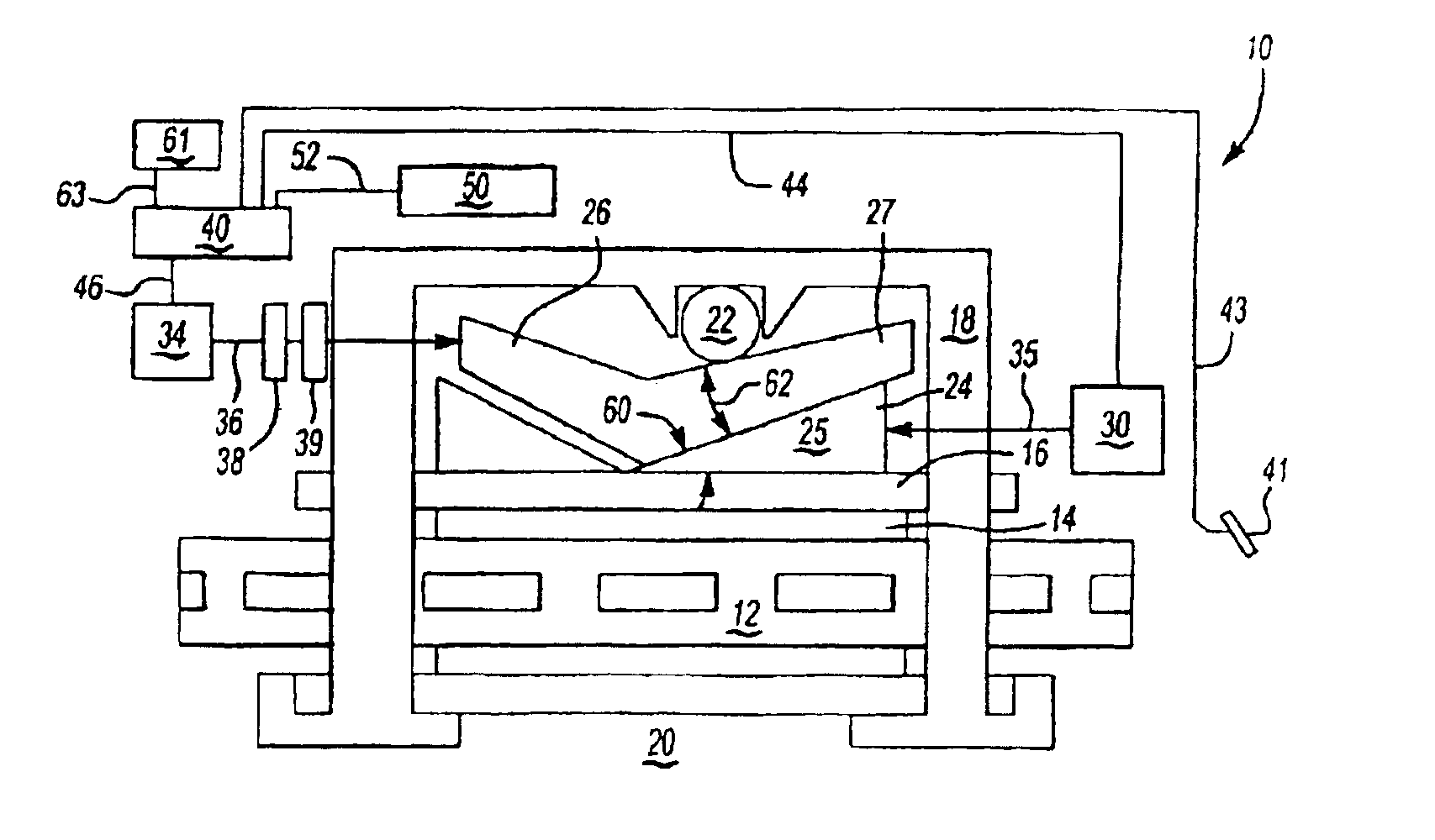
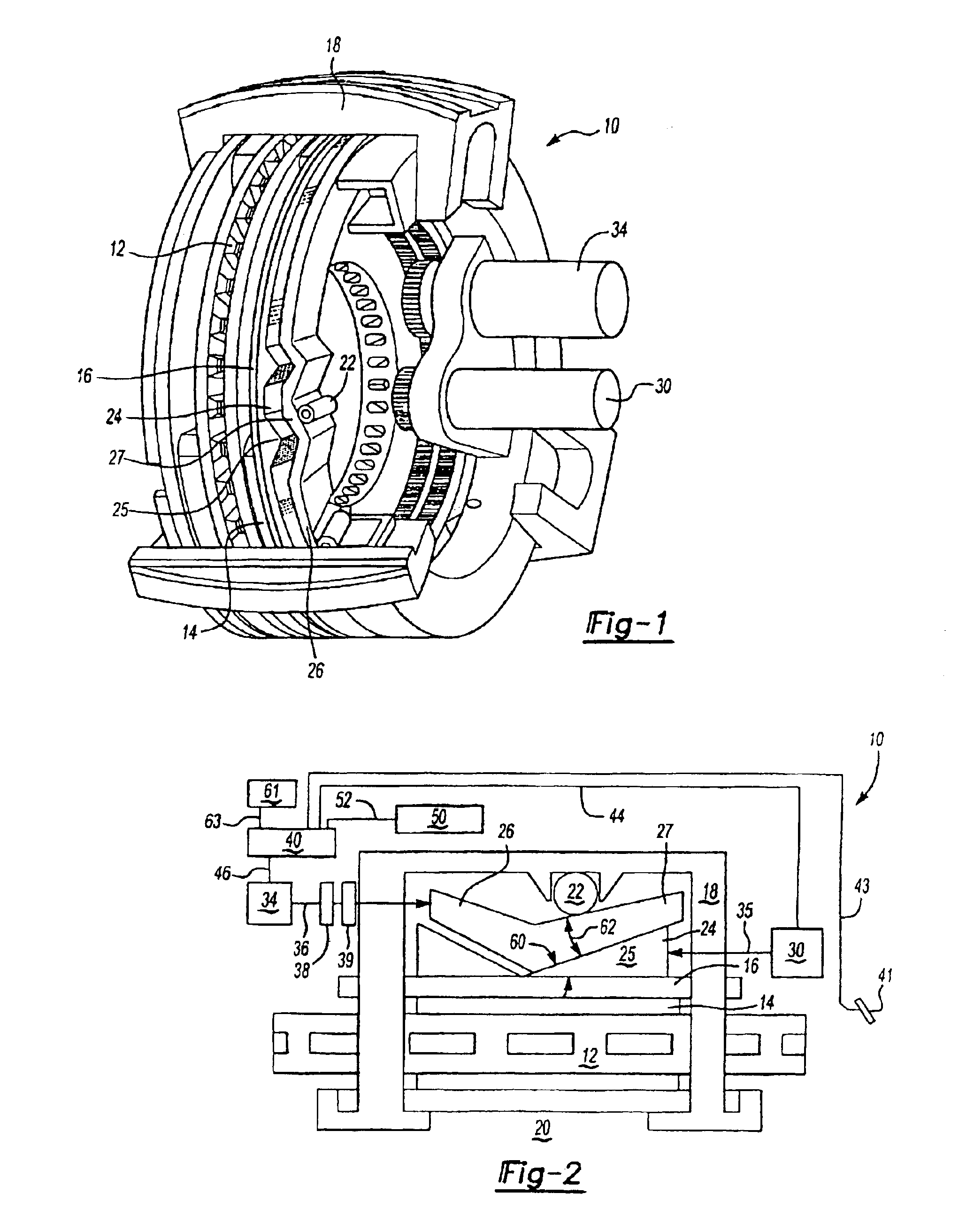
[0027]Referring now to FIGS. 1 and 2, there is shown an electromechanical brake assembly 10 which is made in accordance with the teachings of the preferred embodiment of the invention.

[0028]Particularly, the electromechanical brake assembly 10 includes at least one rotor 12 which is attached to and which selectively rotates with a wheel (not shown) of the selectively movable assembly or vehicle (not shown) into which the brake assembly 10 is operatively disposed within. Further, as shown, the electromechanical brake assembly 10 includes at least one pad member 14 which may selectively engage the movable rotor 12 in a manner which is more fully delineated below and which is effective to brake the selectively movable assembly which operatively contains the electromechanical brake assembly 10. It should be appreciated that multiple pad members 14 may be used within the brake assembly 10 and that a selectively movable assembly, such as a vehicle, may have one brake assembly 10 operativ...


PUM


Abstract

A brake assembly including a brake pad; a selectively movable rotor, a backing plate which is coupled to the brake pad, at least a first roller which is coupled to the backing plate, a caliper, at least a second roller which is coupled to the caliper, a wedge member which is positioned between and which engages the at least first and the at least second roller, and a motor which is coupled to the wedge member and which selectively moves the wedge member, effective to brake a selectively movable assembly.

Description

CROSS-REFERENCE TO RELATED APPLICATIONS[0001]This application is a division of U.S. application Ser. No. 10 / 063,635 filed May 6, 2002, now issued as U.S. Pat. No. 6,752,247.BACKGROUND OF THE INVENTION[0002]1. Field of the Invention[0003]The present invention generally relates to a method and an assembly for braking a selectively movable assembly and more particularly, to a vehicular brake assembly which provides a controllably varying amount of self energization and to a method for braking a selectively movable assembly which provides this controllably varying amount of self energization by the use of a pair of selectively movable wedge members which cooperatively allow a vehicle to be smoothly and efficiently braked with the use of a pair of relatively small electrical motors.[0004]2. Background Art[0005]An electromechanical braking assembly typically 20 provides braking of a selectively movable assembly (such as a vehicle) by the use of a motor which becomes selectively energized ...

Claims


Application Information

Patent Timeline
Patent Type & Authority Patents(United States)
IPC IPC(8): B60T13/74B60T13/00F16D65/14F16D65/18
CPCB60T13/74F16D65/18B60T2270/83F16D2121/24F16D2123/00F16D2125/38F16D2125/48F16D2127/10
Inventor HARTSOCK, DALE LEE
Owner FORD GLOBAL TECH LLC
Why Eureka
Try Eureka