Acoustic assessment of fluids in a plurality of reservoirs

Inactive Publication Date: 2005-09-06
LABCYTE
View PDF42 Cites 70 Cited by
  • Summary
  • Abstract
  • Description
  • Claims
  • Application Information

AI Technical Summary

Benefits of technology

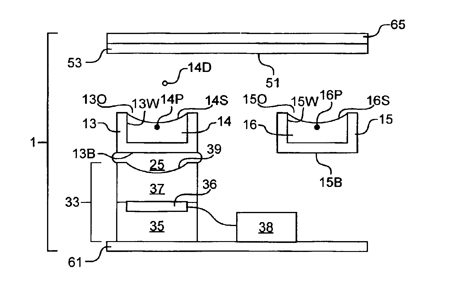
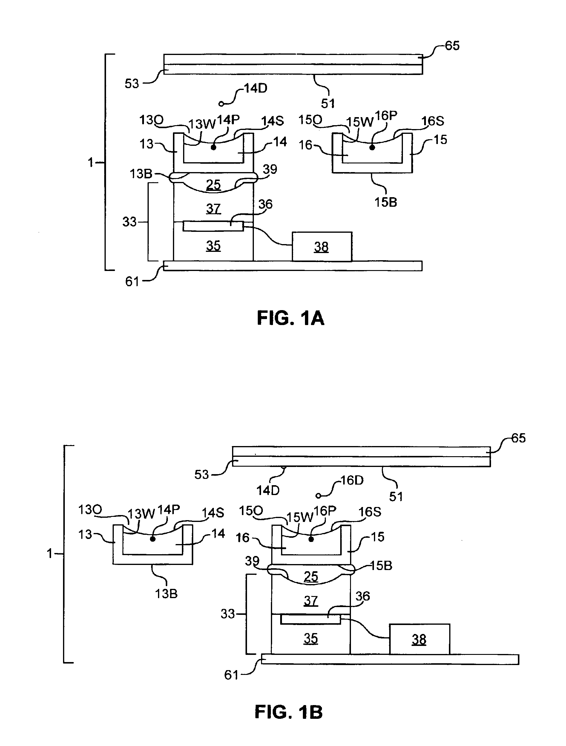
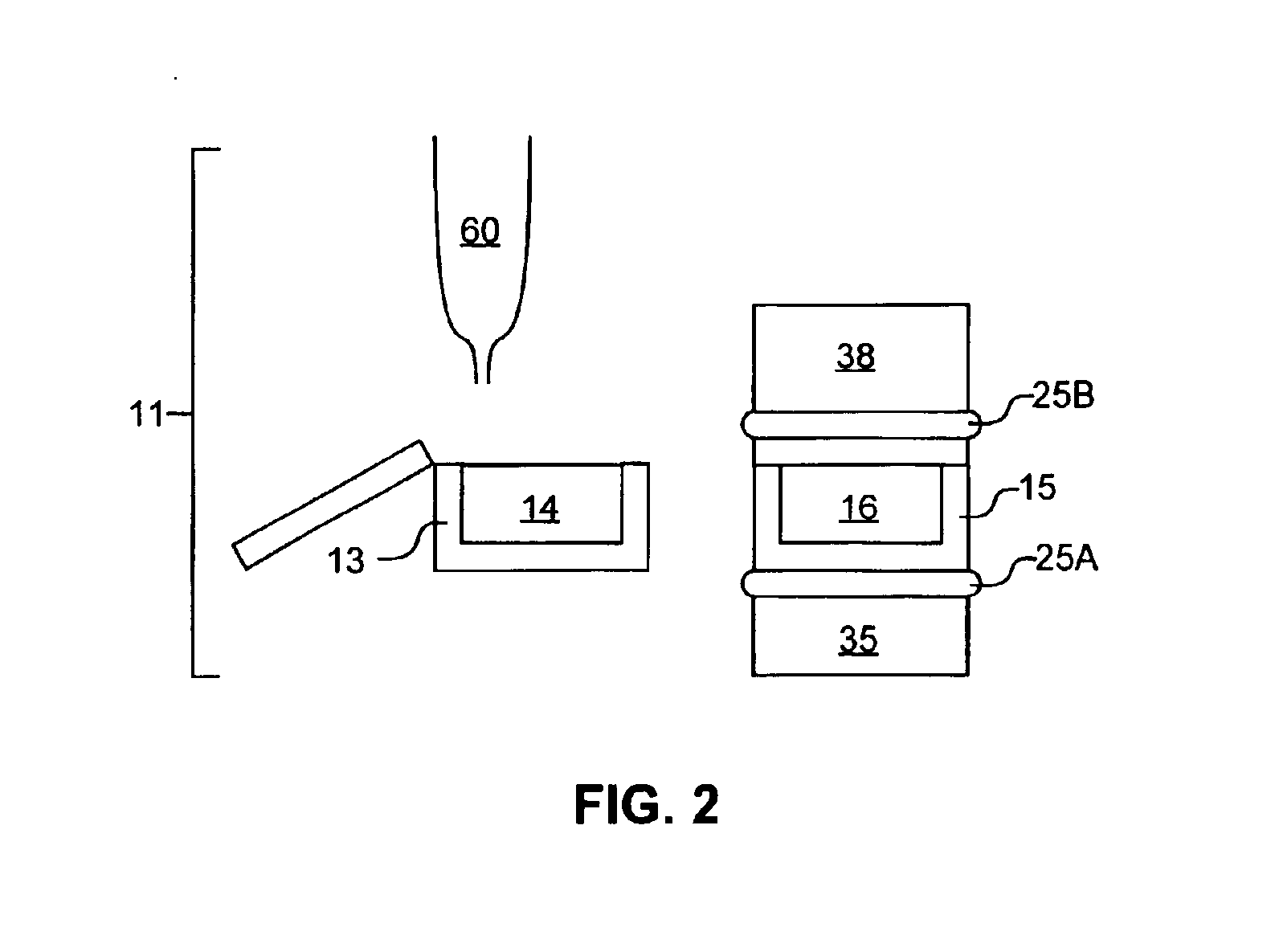
[0018]In some instances, an ejector and a means for positioning the ejector to eject fluid from any of the reservoirs may be provided. Such an ejector may employ focused acousti

Problems solved by technology

Otherwise, the integrity of the process and the quality of the resulting product is compromised.
Quality control of the starting materials is a particularly important issue in combinatorial synthesis procedures.
Should any of the starting compounds contain an unacceptable level of a contaminant or exhibit an unacceptable degree of degradation, the resulting compound may be rendered useless.
In effect, all starting compounds employed for the batch synthesis would be wasted.
This is particularly problematic when the one or more of the starting compounds are rare or expensive.
If any one of the candidate compounds is compromised in quality, however, the accuracy and reliability of the assessment may be reduced.
Thus, further testing may be necessary, adding significantly to the overall time and cost associated with the combinatorial testing process.
Many of these techniques possess inherent drawbacks that must be addressed, however, before the fluid dispensing accuracy required for the combinatorial methods can be achieved.
Tubing, in particular, can entrap air bubbles, and nozzles may become clogged by lodged particulates.
As a result, system failure may occur and cause spurious results.
Furthermore, cross-contamination between the reservoirs of compound libraries may occur due to inadequate flushing of tubing and pipette tips between fluid transfer events.
Cross-contamination can easily lead to inaccurate and misleading results.
Regardless of the dispensing technique used, however, inventory and materials handling limitations generally dictate the capacity of combinatorial methods to sy

Method used


Image

  • Acoustic assessment of fluids in a plurality of reservoirs
  • Acoustic assessment of fluids in a plurality of reservoirs
  • Acoustic assessment of fluids in a plurality of reservoirs

Examples


example 1

[0137]Measurements were made to determine the usefulness of acoustic echoing to carry out in situ measurement of fluid properties. About 45 uL of fluid comprised of a solution containing 70% DMSO and 30% water was pipetted into a well of a polypropylene well plate containing 384 wells. The fluid exhibited a concave fluid surface in the well. A transducer was aligned at approximately the center of the well and the transducer height was optimized for ejection. A toneburst was applied to the fluid as to perturb the fluid surface and to produce a subthreshold ejection cone. A toneburst was then applied to the transducer (10 MHz, F#2), of 10 MHz center frequency, and of energy approximately 1.5 dB below ejection threshold. The initial cone produced contained many spatial frequencies, which propagated as capillary waves outward toward the well walls. Then, the waves were partially reflected from the well walls through the center of the well, toward the opposing well walls, again reflected...

example 2

[0141]Measurements similar to those described in Example 1 were made except that a fluid containing 100% DMSO was employed in place of the solution containing 70% DMSO and 30% water. FIG. 8 is a graph that plots the measured echo delay time for this fluid as well as for the solution containing DMSO and water mixture as a function of time after the toneburst. Since optimal delay time is slightly different for the two fluids, the data for the mixture is plotted with an arbitrary offset in the vertical direction for ease in visual comparison.

[0142]The data for the two fluids were fitted to exponentially decaying sinusoidal waveforms, in the time period 25 millisecond

example 3

[0144]A well of a well plate is filled with a fluid. A transducer is aligned at approximately the center of the well, and the transducer height is optimized for ejection. A toneburst is applied to the fluid as to perturb the fluid surface and to produce a superthreshold ejection cone. As a result, a droplet is formed and separated from the ejection cone.

[0145]Before, during and after the formation of the ejection cone, a series of echo pulses is generated to monitor the perturbation of the fluid surface. As a result, the formation of the droplet is monitored through a series of such echo events. EXAMPLE 4

[0146]A well of a well plate is filled with a fluid. A transducer is aligned at approximately the center of the well, and the transducer height is optimized for ejection. A series of toneburst is applied to the fluid as to perturb the fluid surface and to produce an ejection cone. Immediately before, during and after the formation of the ejection cone, a series of echo pulses is gen...


PUM


Abstract

The invention provides devices and methods for acoustically assessing the contents of a plurality of reservoirs that are typically provided as an array. An acoustic radiation generator is employed for generating acoustic radiation having an image field of a size sufficient to interrogate a plurality of selected reservoirs at one time. The generator is placed in acoustic coupling relationship via a fluid acoustic coupling medium to the selected reservoirs, and acoustic radiation generated by the generator is transmitted through the coupling medium, an exterior surface of the selected reservoirs, and the selected reservoirs. A characteristic of the transmitted acoustic radiation is analyzed so as to assess the contents of each of the selected reservoirs. Fluid may be ejected from the selected reservoirs according to the assessment. Optionally, a means is provided for removing fluid acoustic coupling medium from the exterior surface after acoustic assessment.

Description

CROSS-REFERENCE TO RELATED APPLICATIONS[0001]This is a continuation-in-part of U.S. patent application Ser. No. 10 / 010,972, filed Dec. 4, 2001 now abandoned, the disclosure of which is incorporated herein by referenceTECHNICAL FIELD[0002]The invention relates generally to the use of acoustic energy to assess the contents of a plurality of reservoirs. In particular, the invention relates to devices and methods for acoustically assessing the contents of a plurality of reservoirs in order to enhance accuracy and precision in dispensing fluids from the reservoirs. The invention is particularly suited for use in conjunction with high-speed combinatorial synthetic and analytical systems that employ biomolecular libraries containing a large number of different fluid reservoirs.BACKGROUND[0003]The discovery of novel and useful materials depends largely on the capacity to make and characterize new compositions of matter. As a result, recent research relating to novel materials having useful ...

Claims


Application Information

Patent Timeline
IPC IPC(8): B01L3/02G01N29/02G01F23/296G01N29/22G01N29/28G01N35/00G01N35/10C40B60/14
CPCB01L3/0268G01F23/296G01F23/2968G01N29/02G01N29/22G01N29/222G01N29/28B01J2219/00362B01J2219/00702B01L2200/143B01L2300/0819B01L2400/0436B01L2400/0439C40B60/14G01N35/1016G01N2035/00158G01N2291/02818G01N2291/02836G01N2291/02881G01N2291/2695
Inventor MUTZ, MITCHELL W.ELLSON, RICHARD N.FOOTE, JAMES K.
Owner LABCYTE
Why Eureka
Try Eureka