Laser image projector

a projector and laser technology, applied in the field of image projectors, can solve problems such as system encumbran

Inactive Publication Date: 2005-09-06
EASTMAN KODAK CO
View PDF12 Cites 39 Cited by
  • Summary
  • Abstract
  • Description
  • Claims
  • Application Information

AI Technical Summary

Benefits of technology

[0008]The present invention has the advantage that a projection display is provided that does not need a projection optical system.

Problems solved by technology

However, such systems are encumbered by the weight and size of the projection optical system and are restricted to imaging upon a single screen.
However, this system relies upon extensive beam combining optics to integrate the light paths and project image at a plurality of screens.

Method used


Image

  • Laser image projector
  • Laser image projector
  • Laser image projector

Examples


Embodiment Construction

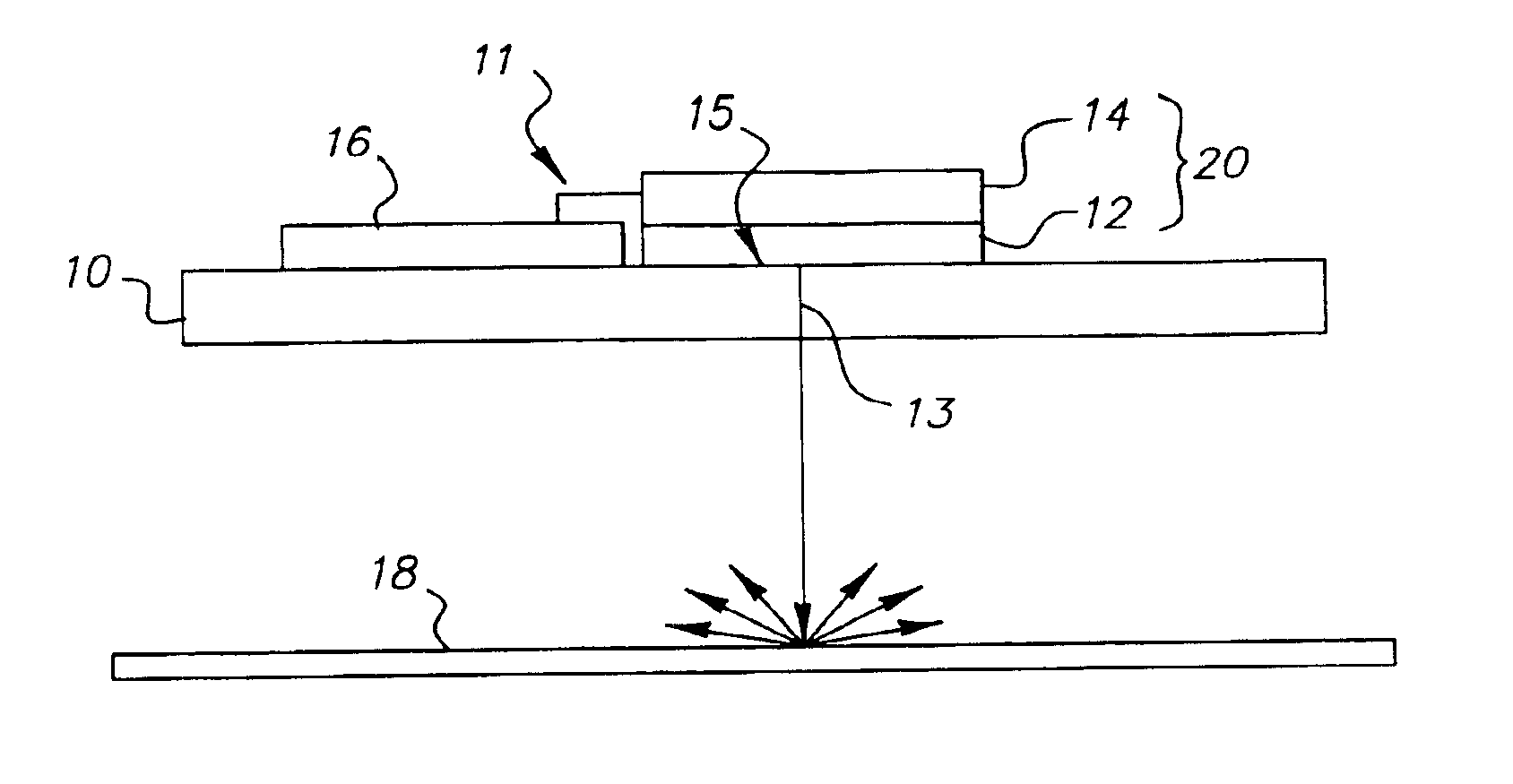
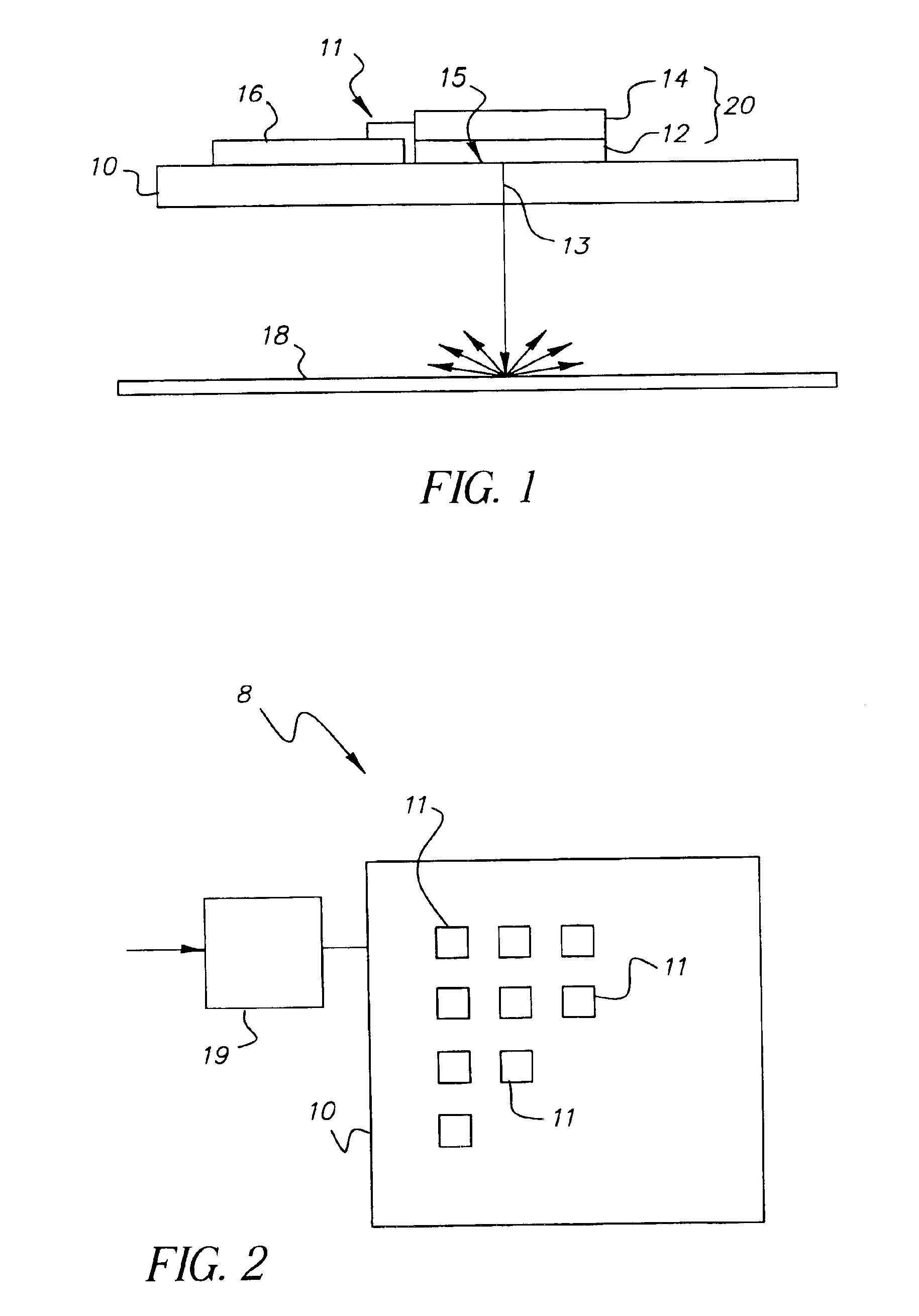
[0020]Referring to FIG. 1, an individually addressable laser pixel 11 includes an organic laser 12 that is optically pumped by light from an OLED 14 formed on a substrate 10 and electrically controlled through a circuit 16. In a passive matrix projector, circuit 16 simply comprises electrical conductors. In an active matrix projector circuit 16 contains active electronic elements such as transistors and capacitors.

[0021]The OLED 14 emits incoherent light 15 to optically pump the organic laser 12 that, in turn, emits laser light 13 perpendicular to the substrate and travels to expose an element such as a light diffusing projection screen 18 where the emitted light is diffused and becomes visible to an observer (not shown). The light diffusing projection screen 18 may be either transmissive or reflective to enable either rear or front viewing.

[0022]Referring to FIG. 2, a laser projector 8 includes an array of individually addressable laser pixels 11 controlled by a controller 19. The ...


PUM


Abstract

A laser image projector includes a substrate; and a two dimensional array of individually addressable laser pixels formed on the substrate for emitting an imagewise beam of laser light perpendicular to the substrate, each of the laser pixels including an addressable organic light emitting diode (OLED) and an organic vertical cavity laser that is arranged to be pumped by the OLED.

Description

CROSS REFERENCE TO RELATED APPLICATIONS[0001]Reference is made to U.S. Ser. No. 10 / 272,093 filed Oct. 16, 2002 by Spoonhower et al., entitled ORGANIC LASER CAVITY ARRAYS.FIELD OF THE INVENTION[0002]The present invention relates to the field of image projectors.BACKGROUND OF THE INVENTION[0003]Image projection devices are well known and have been used for many years. Such systems typically rely upon an image modulator and an optical projection means to project the image upon a diffuse screen, whereon it is viewed by an observer. Image modulators were originally hard copy media based, for example, films such as transparencies and motion picture film. More recently, soft copy projectors have become available and are based upon, for example micro electromechanical systems or liquid crystal devices as well as laser projection systems, for example see U.S. patent application 2003 / 0039036 A1 by Kruschwitz et al., published Feb. 27, 2003. In any case, the image modulator creates an image pl...

Claims


Application Information

Patent Timeline
Patent Type & Authority Patents(United States)
IPC IPC(8): H04N9/31H05B33/02G09G3/20G09G3/32H01L51/50H01S3/08H01S3/091H01S3/0915H01S3/17
CPCH04N9/3129
Inventor COK, RONALD S.SPOONHOWER, JOHN P.MANICO, JOSEPH A.COVANNON, EDWARDPATTON, DAVID L.
Owner EASTMAN KODAK CO
Why Eureka
Try Eureka