Apparatus and method for applying reinforcement material to a surgical stapler

a technology of reinforcement material and surgical stapler, which is applied in the field of surgical staple devices, can solve the problems of slow healing, too fragile tissue being sealed to securely hold the staples in place, and the procedure is much faster than before, and achieves the effect of accurate sizing of reinforcement material and simple manufacturing

Inactive Publication Date: 2005-09-06
WL GORE & ASSOC INC
View PDF11 Cites 1529 Cited by
  • Summary
  • Abstract
  • Description
  • Claims
  • Application Information

AI Technical Summary

Benefits of technology

[0012]The present invention is an apparatus and method used to apply a self-adherent strip of bio-compatible, staple line reinforcement material onto a working surface of a surgical stapler. The apparatus effectively contains and supports the self-adherent, reinforcement material during sterilization and shipment. At the point of use, the apparatus provides a simple method for applying the self-a

Problems solved by technology

This procedure is much faster than using a conventional process of cutting with scissors or a scalpel and then laboriously sealing the incision with sutures.
However, in certain circumstances the tissue that is being sealed is too fragile to securely hold the staples in place.
In these instances, the tissue will tend to rip at or near the staple lines, slowing healing and possibly leading to serious complications.
Diseased lung tissue is very fragile and, in extreme cases, will easily tear through unprotected staple lines.
In laparoscopic procedures, the sleeve surrounding the stapler jaw and anvil can interfere with the trocar.
There are a number of serious deficiencies with the Francis et al. apparatus.
First, the use of bovine pericardium material is undesirable since this material requires preparation prior to use and must be kept moist to prevent embrittling and cracking when the staples are fired.
Thus staples must be fired soon after mounting of the reinforcement material, limiting the abil

Method used


Image

  • Apparatus and method for applying reinforcement material to a surgical stapler
  • Apparatus and method for applying reinforcement material to a surgical stapler
  • Apparatus and method for applying reinforcement material to a surgical stapler

Examples


example 2

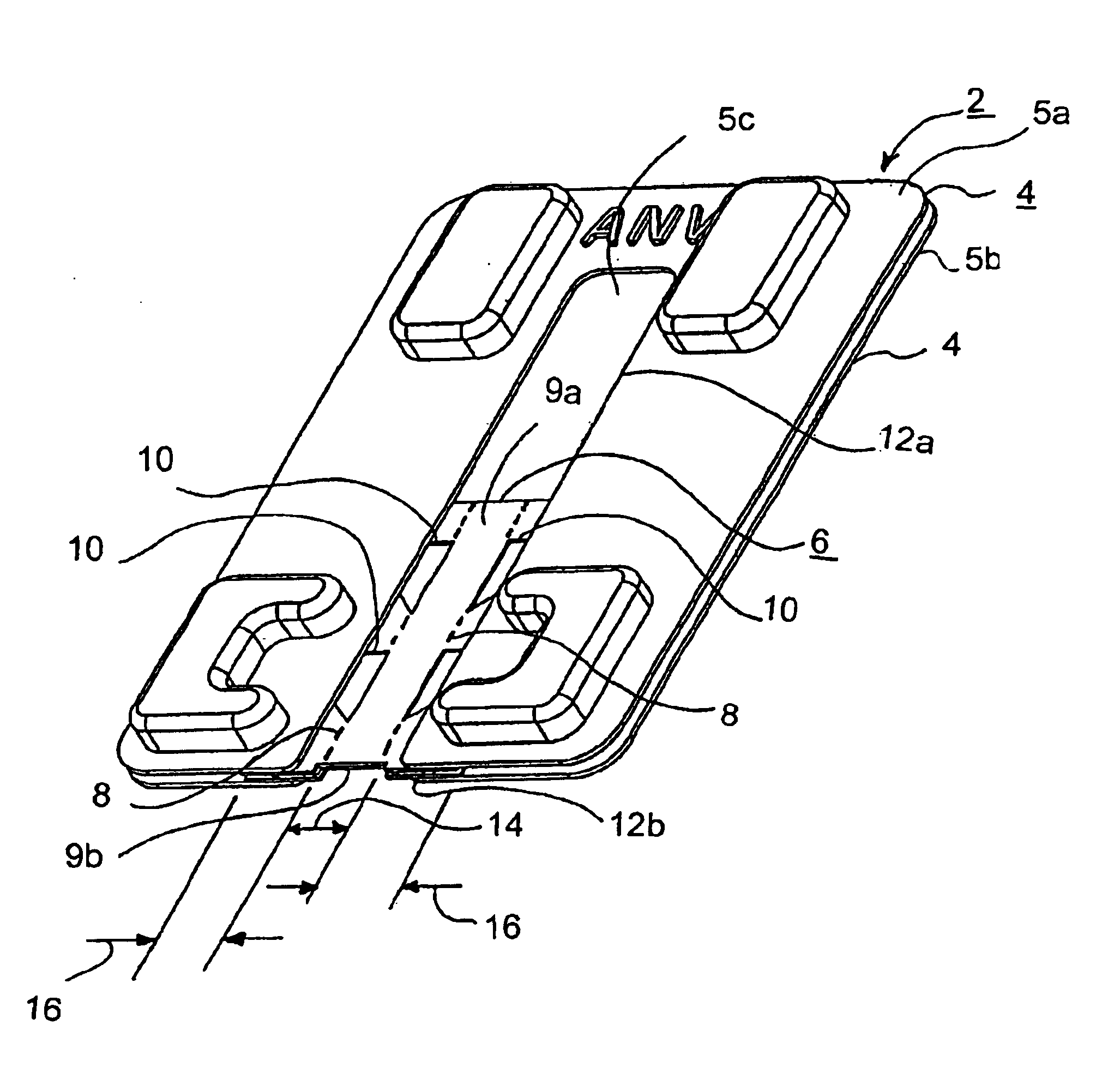
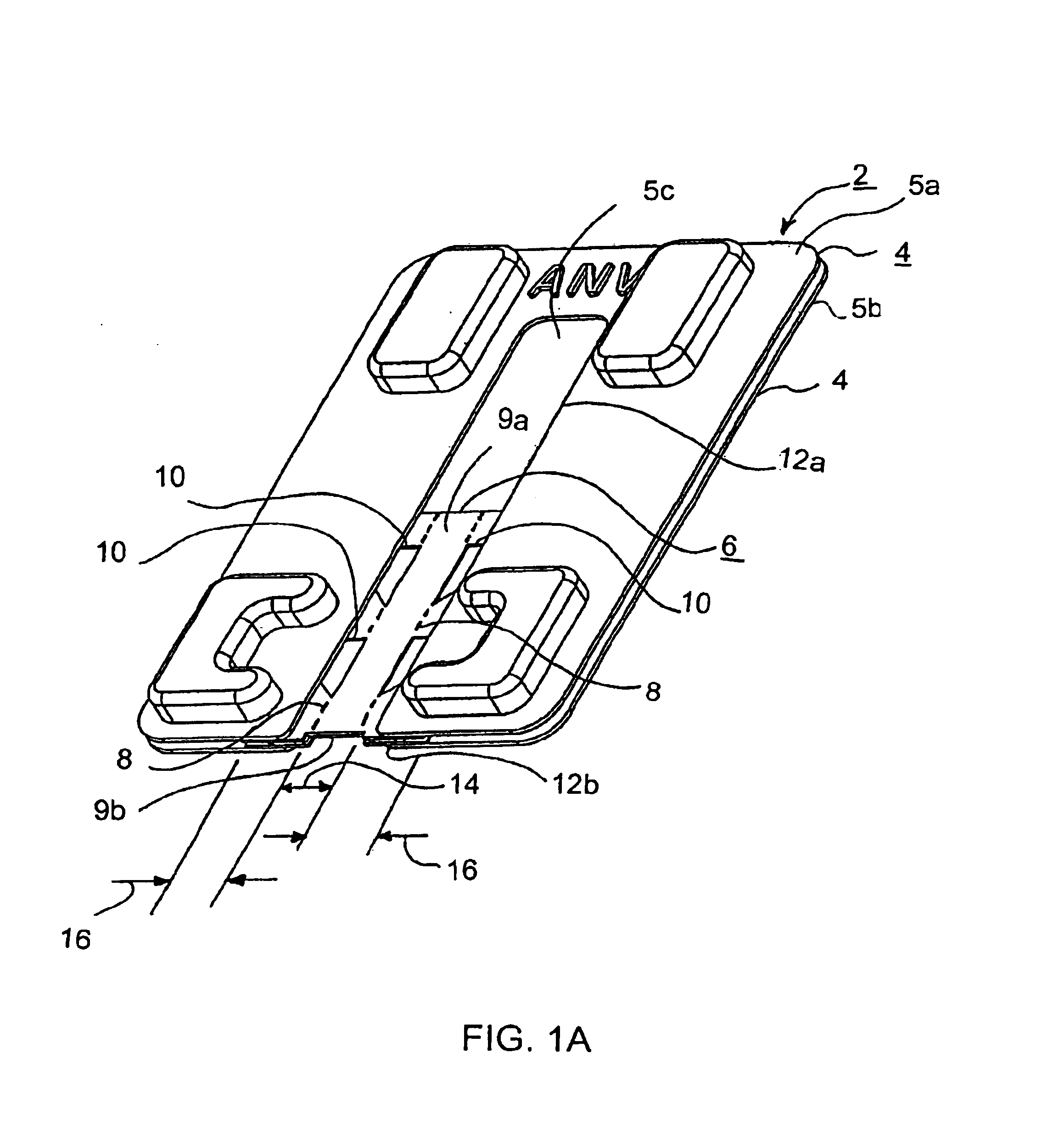
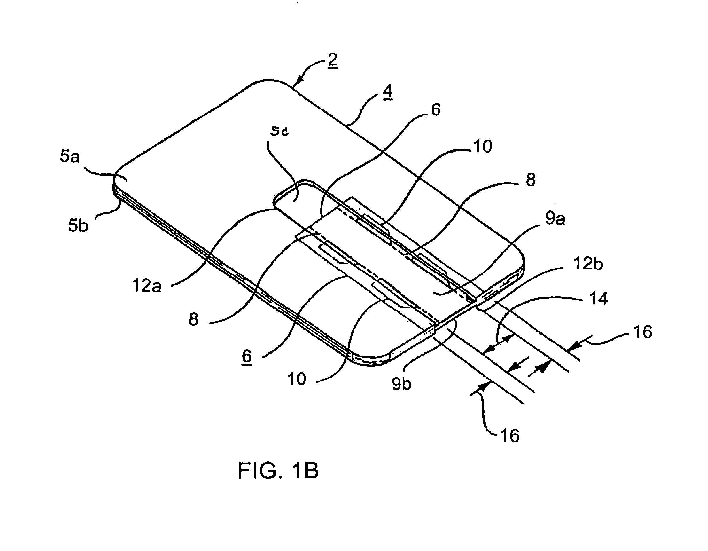
[0088]A package was constructed to apply surgical staple reinforcement material to the arms of a Model ETS 45 surgical stapler available from Ethicon, Somerville, N.J. The basic configuration of this example is shown in FIG. 14. Shown is a package 2 for applying surgical staple reinforcement material to the arms of a surgical stapler. The package 2 comprised an application card 4, with a first portion 5a, a second portion 5b, and a landing 110 against support layer 5C. The package 2 further comprised a reinforcement material 6 having a first portion 112 adapted to be attached to the jaws of the aforementioned family of surgical staplers. The reinforcement material 6 had a second portion 114, attached to the application card 4. Tear lines 8 separated the first portion 112 and second portions 114 of the reinforcement material 6. An adhesive 116 was attached to the first portion 112 and second portion 114 of the reinforcement material 6. The attachment of the second portion 114 to the ...

example 3

[0100]A package was constructed to apply surgical staple reinforcement material to the arms of a Model EZ 45 surgical stapler available from Ethicon, Somerville, N.J. This package was similar to the package of Example 2 with the exception of details designed to accommodate the raised scalpel blade stop located on astapler cartridge. Shown on FIG. 17 is the cartridge portion of the reinforcement material 6 of the present example. Shown is the first removable portion 112 and the second retained portions 114 of the reinforcement material 6. Within the removable portion 112 was a clearance hole 186, designed to provide clearance for the raised scalpel blade stop located on the Model EZ 45 stapler cartridge. Elements 188 and 190 locate the approximate center of the oval shaped clearance hole 186, which had a long vertical axis of about 2.3 mm and a shorter horizontal axis of about 1.8 mm. Dimension 188 was about 5.8 mm and dimension 190 was about 15.3 mm. The tear lines on the cartridge ...

example 4

[0104]As has been noted, it may be desirable to include a separate piece of foam or other resilient material with the package of the present invention to aid in reapplying staple reinforcement material that might separate from the stapler arms prior to application and / or to provide a surface against which to improve sealing of the reinforcement material prior to use.

[0105]One example of such resilient material 200 is illustrated in FIG. 19. This material comprised a pentagonal shape of polyether-urethane foam, with about a 1.6 # density acquired from Pacfoam, Costa Mesa, Calif. This foam piece was about 10.5 cm along dimension 202, about 4.5 cm along dimension 204, and 6.5 cm along dimension 206. The foam was approximately 7 mm thick.

[0106]Use of similar resilient material 208 is illustrated in FIGS. 20A through 20D. A stapler assembly 20, having anvil 22 and cartridge 24, with staple reinforcement material 6 applied to each of the anvil 22 and cartridge 24, was positioned around th...


PUM


Abstract

An apparatus and method used to apply a self-adherent strip of bio-compatible, staple line reinforcement material onto a working surface of a surgical stapler. The apparatus effectively contains and supports reinforcement material during sterilization and shipment. At the point of use, the apparatus provides a simple method for applying the reinforcement material to a variety of staplers. Once the reinforcement material is applied, no excess material remains attached to the stapler thus post-attachment removal of excess material is avoided. The apparatus is simple to manufacture, accommodates a wide variety of reinforcement material shapes and configurations, allows for accurate sizing of the reinforcement material to a variety of stapler jaws, and provides a very low profile package to reduce packaging, shipping, and storage costs.

Description

FIELD OF THE INVENTION[0001]The present invention relates to surgical staple devices and more specifically to an improved apparatus for applying reinforcing materials to surgical staple devices.BACKGROUND OF THE INVENTION[0002]One of the more commercially successful innovations in surgical procedures in recent years is the development of surgical stapler devices. These devices are designed to seal or simultaneously cut and seal an extended segment of tissue in a patient, vastly reducing the time and risks of such procedures. Typically, a surgical stapler comprises two stapler arms, one containing two or more lines of multiple staples (“cartridge” or “jaw”) and a second containing corresponding means to bend each of the staples into a closed position (“anvil”). For most applications, a surgical blade is included in the device to quickly sever tissue between the lines of staples. Those stapler devices employing a cutting blade are referred to as “anastomotic staplers” and those used w...

Claims


Application Information

Patent Timeline
IPC IPC(8): A61B19/00A61B19/02A61B17/068A61B17/072
CPCA61B17/07207A61B19/026A61B17/07292A61B50/30
Inventor PALACIOS, EDWARD M.TORREZ, RAYMOND P.
Owner WL GORE & ASSOC INC
Why Eureka
Try Eureka