Closure device

a technology of a sealing device and a stent, which is applied in the field of stents, can solve the problems of potential risk of a sealing member being deployed inside the blood vessel, unintentional introduction of sealing members or haemostatic materials into the blood vessel itself, and damage to the inner vessel wall of the locating member,

Inactive Publication Date: 2005-09-06
ST JUDE MEDICAL COORDINATION CENT
View PDF15 Cites 99 Cited by
  • Summary
  • Abstract
  • Description
  • Claims
  • Application Information

AI Technical Summary

Benefits of technology

[0009]Thus, there is a need in the art for a closure device that eliminates the risk that any sealing material unintentionally is introduced into a vessel. At the same time, the sealing material of such a closure device should not obstruct the fluid flow inside the vessel once the sealing operation has been completed.
[0010]The present invention discloses how a percutaneous incision leading to a vessel can be sealed without the risk that any sealing material unintentionally is introduced into the vessel itself. The closure device according to the present invention comprises basically an elongated insertion assembly and a charge of haemostatic material, which is contained in the distal portion of the insertion assembly. The insertion assembly, in turn, comprises a stationary part and a retractable part, which is in slidable engagement with the stationary part. The first step in a sealing operation is to connect the insertion assembly

Problems solved by technology

However, a drawback with this sealing device is the potential risk that the locating members damage the inner vessel wall during the positioning operation, i.e. when a user retracts the locating device until he or she feels the resistance from the inner vessel wall.
A more general problem encountered with closure devices of the type shown in U.S. Pat. No. 6,368,341 is the potential risk that a sealing member is deployed inside the blood vessel, instead of in the incision channel leading to the puncture hole in the vessel.
This may for instance occur if a user misinterprets a resistance to retracting movement in the locating device as coming from the inner vessel wall, or accidentally pushes the whole haemostatic closure device too far into the incision channel before deploying the sealing member.
The potential problem that a sealin

Method used


Image

  • Closure device
  • Closure device
  • Closure device

Examples


first embodiment

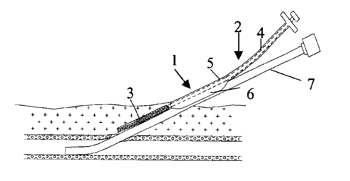
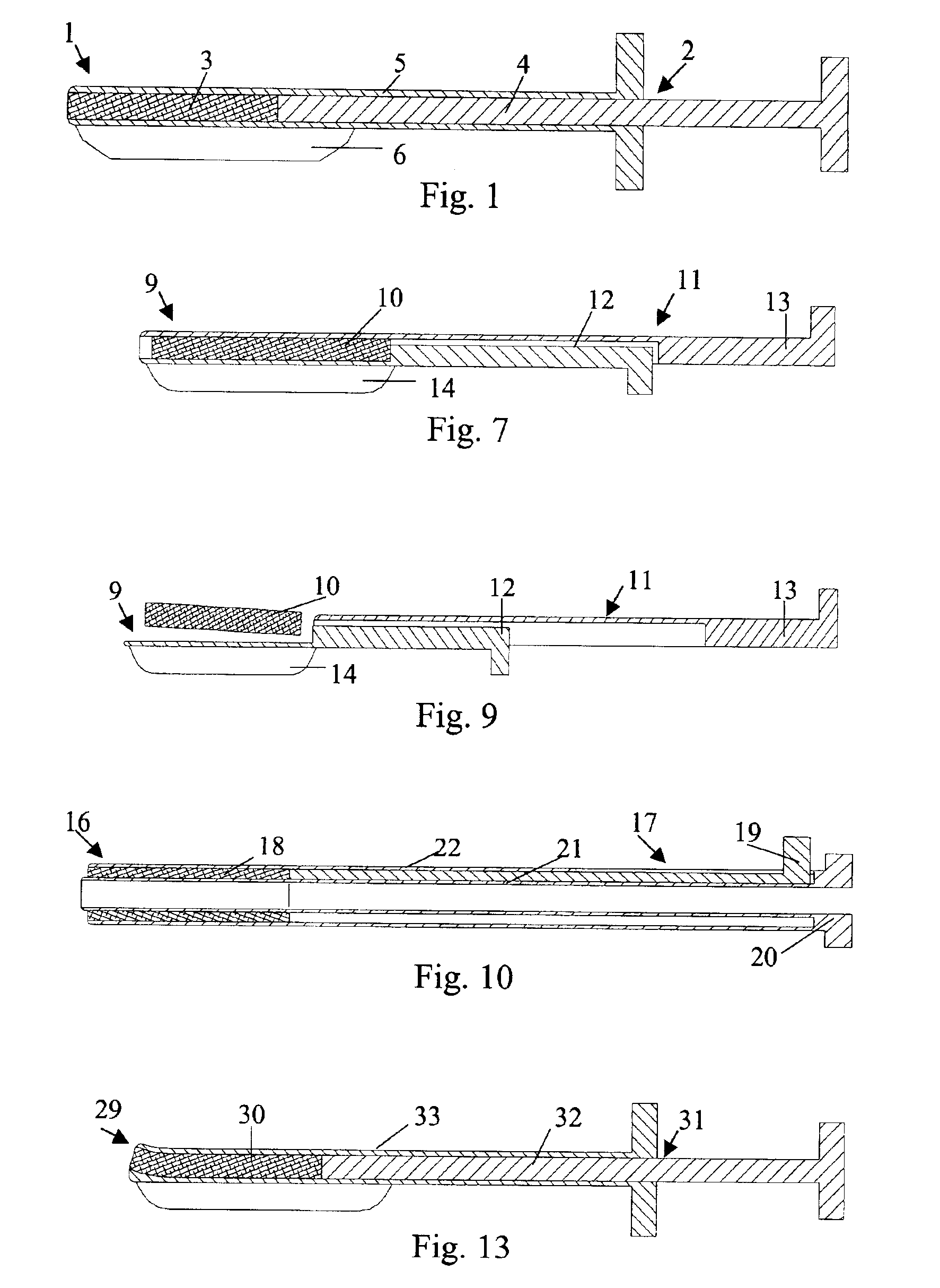
[0025]In FIG. 1 is illustrated a closure device 1 according to the present invention. The closure device 1 comprises an elongated insertion assembly 2 and a haemostatic or sealing material 3, which is contained in the distal portion of the insertion assembly 2. Preferably the haemostatic material 3 is impregnated or in some other way provided with a suitable clotting agent such as thrombin. The insertion assembly 2, in turn, comprises two parts, an elongated stationary part 4 and an elongated retractable part 5. Basically, the stationary part 4 has the shape of a rod, the distal end of which is in contact with the haemostatic material 3, and the retractable part 5 is in the form of a hollow sheath, which is in slidable engagement with the outside of the stationary part 4. Parts 4 and 5 may be made from any suitable material, such as plastic or metal. In FIG. 1, the closure device 1 is depicted in an initial state, with the distal portion of the retractable part 5 extending from the ...

third embodiment

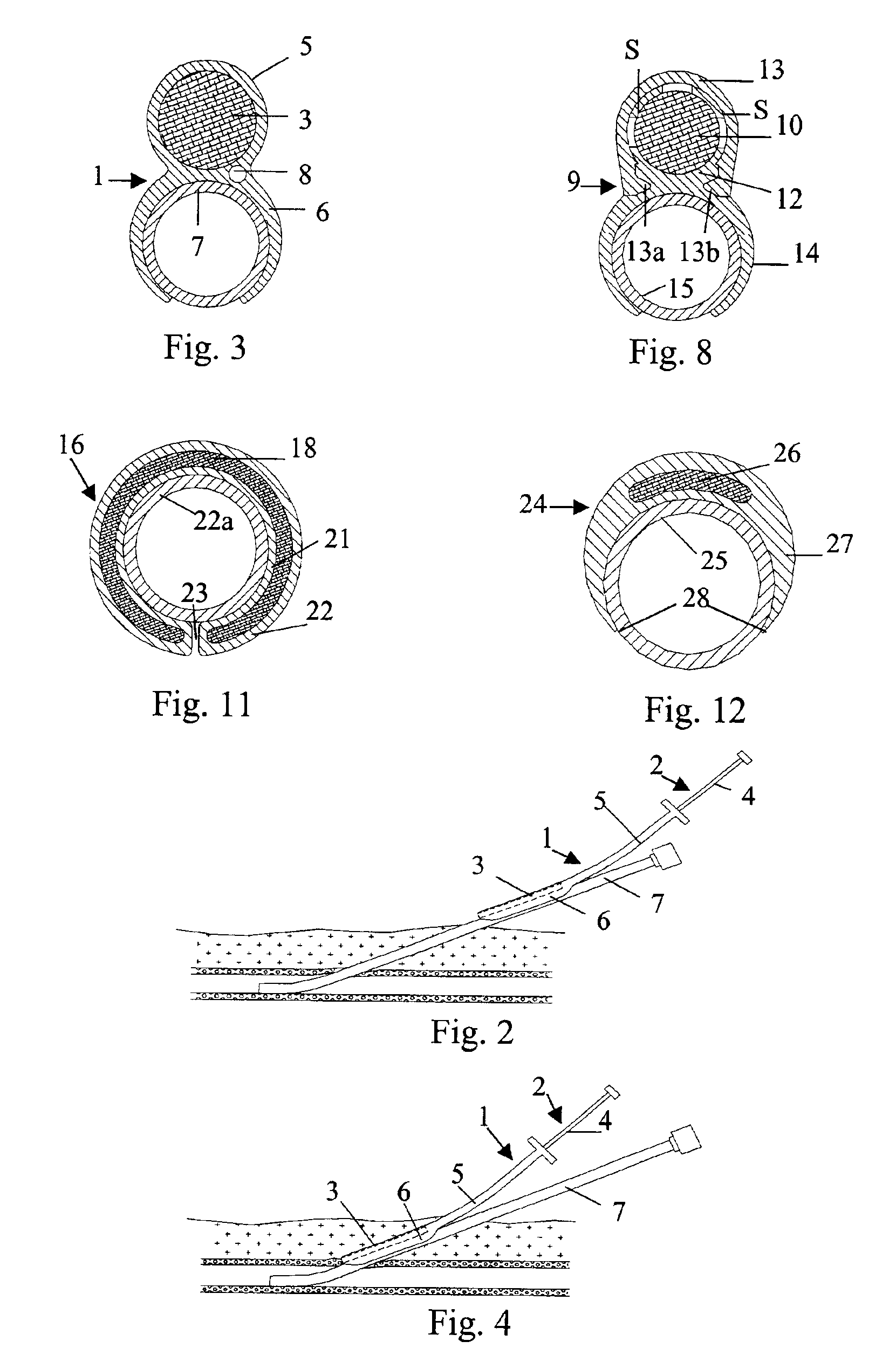
[0037]In the embodiments shown in FIG. 1 and FIG. 7, respectively, the closure devices have been provided with an attachment means, such as attachment members 6 and 14, that virtually operates a separate part of the insertion assembly, i.e. the elongated insertion assembly slides as a separate part on the outside of the introducer. This is not to say that the attachment member actually is provided as a separate part to an existing insertion assembly, or that the attachment member has to be manufactured in a separate manufacturing step. In FIG. 10 is shown a closure device 16. The closure device 16 comprises an elongated insertion assembly 17 and a charge of a haemostatic material 18. The insertion assembly 17, in turn, comprises an elongated stationary part 19 and an elongated retractable part 20. The retractable part 20 is in the form of a hollow sheath having an inner wall 21 and an outer wall 22. The charge of haemostatic material 18 is disposed between the inner wall 21 and the ...

fourth embodiment

[0039]In FIG. 12 is shown the cross-section of a closure device 24 connected to an introducer 25. The closure device 24 comprises a haemostatic material 26, which is contained in the distal portion of a retractable part 27. In this embodiment, the retractable part 27 has basically the form of a hollow sheath, with a rather large portion being cut away along its length. This cut-away portion (indicated with reference numeral 28) replaces the more narrow slit 23 described above in connection with FIG. 10 and FIG. 11. The wall of the hollow sheath that basically constitutes the retractable part 27 becomes thinner towards its longitudinal edges, thereby making it easy to thread the insertion assembly onto an introducer. Further, a cavity, which extends along the length of the retractable part 27, is provided opposite to the cut-away portion 28, where the wall of the retractable part 27 has its largest thickness. This cavity, in which the haemostatic material 26 is contained, occupies on...


PUM


Abstract

The invention provides a closure device (1) for sealing an incision channel leading through a vessel wall and into the vessel. The closure device (1) comprises a haemostatic material (3), which is contained in the distal end of an elongated insertion assembly (2). The insertion assembly (2), which comprises a stationary part (4) and a retractable part (5) being slidably movable with regard to each other, is adapted to be attached to an introducer (7) being in position in the incision channel, so that the insertion assembly (2) can be slid along the introducer (7) until the distal end of the insertion assembly (2) is in contact with the vessel wall, where the haemostatic material (3) is delivered in the incision channel by a retracting movement of the retractable part (5).

Description

BACKGROUND OF THE INVENTION[0001]The present invention relates generally to a closure device for sealing a percutaneous puncture in a vessel, in particular a closure device with which haemostatic material is introduced in the incision channel leading to the puncture hole in the vessel wall, thereby sealing the percutaneous puncture without obstructing the flow inside the vessel and without the risk that the haemostatic material unintentionally is introduced into the vessel.[0002]During certain types of medical surgery or treatment, an introducer is used to access the vascular system of a patient. The introducer is inserted through the wall of a blood vessel in order to obtain access to the vascular system and may thereafter be used for guiding medical instruments such as catheters, guide wires and the like. After the completion of the medical procedure, there will be an incision or a wound in the wall of the blood vessel corresponding to the size of the introducer. The bleeding from...

Claims


Application Information

Patent Timeline
IPC IPC(8): A61B17/00A61B17/34A61M25/01A61B17/04
CPCA61B17/0057A61B17/00491A61B17/3421A61B2017/00637A61B2017/00654A61M25/01
Inventor ANG.KERFELDT, DAN
Owner ST JUDE MEDICAL COORDINATION CENT
Why Eureka
Try Eureka