Device, ammeter and motor vehicle

a technology of ammeter and motor vehicle, which is applied in the direction of measuring devices, magnetic measurements, instruments, etc., can solve the problems of interference, inability to ensure electrical isolation between the measuring circuit and the main circuit, and undesirable additional self-inductance, so as to reduce the dependency on inhomogeneous interference fields, suppress interference fields, and use magnetic field measurements.

Inactive Publication Date: 2005-09-06
ROBERT BOSCH GMBH
View PDF5 Cites 33 Cited by
  • Summary
  • Abstract
  • Description
  • Claims
  • Application Information

AI Technical Summary

Benefits of technology

[0006]The device according to the present invention, the ammeter according to the present invention and the motor vehicle according to the present invention having the features of the subordinate claims have the advantage over the related art that the useful magnetic field measurement is impaired to a lesser degree by magnetic interference fields. This makes it possible to suppress the interference field. It is also possible to dispense with magnetic shielding, while simultaneously reducing the dependency on inhomogeneous interference fields.
[0007]This makes it possible to reduce or eliminate shielding measures, which results in a significant cost advantage.
[0008]It is further advantageous to provide a third sensor means, and for the first sensor means and the third sensor means to be provided in locations where the useful magnetic field is more or less uniform, at least in terms of actual amount. This enables a possible inaccuracy in the position of the main sensors to be detected and electrically compensated through suitable signal analysis, thus simplifying assembly and adjustment. This method may also be used to compensate the offset of the sensor means.
[0009]It is further advantageous to provide the second sensor means in the middle between the first and third sensor means. This makes it even easier to detect or compensate the positioning accuracy of the main sensors.
[0010]It is further advantageous to provide the conductor with a round cross-section. As a result, the magnetic field generated outside the conductor by the current flowing within the conductor is only slightly dependent on the frequency of the electrical current.
[0011]It is further advantageous to provide a magnetic field sensor, in particular, a Hall sensor, a lateral magnetotransistor or a magnetoresistive resistor as the sensor means. This makes it possible to easily and economically sense the current via the magnetic field generated by the current flow, sensor means provided in this manner also taking up less space.

Problems solved by technology

Their high power loss and additional self-inductance are undesirable, especially at high amperages.
In addition, they do not ensure electrical isolation between the measuring circuit and the main circuit.
However, a problem with the use of magnetic field sensors to measure current is that interference, i.e., stray, fields of additional current conductors located adjacent to the conductor to be measured exist or are generated by rotating magnetic fields in the vicinity of generators.
This makes it difficult to discriminate between the magnetic field to be measured by the magnetic field sensor and parasitic stray fields in the surrounding area.
However, shielding for highly sensitive sensors is very complex and expensive.
Magnetic circuits are also expensive and, in addition, not only take up a great deal of mounting space but are difficult to assemble.
A further disadvantage of magnetic circuits is the fact that they have a tendency to become saturated and thus introduce a certain non-linearity between the amperage and magnetic field strength into the measurement.

Method used


Image

  • Device, ammeter and motor vehicle
  • Device, ammeter and motor vehicle
  • Device, ammeter and motor vehicle

Examples


first embodiment

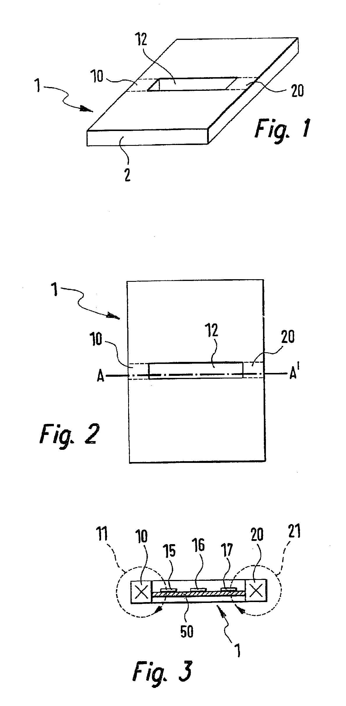
[0019]FIG. 1 shows a perspective representation of a conductor arrangement 1, i.e., a conductor 1, according to a Conductor 1 has a cross-section 2 that is modified in the area of a slot 12. In the area of slot 12, the cross-section that determines the current flow is limited to only a first section 10 and a second section 20.

[0020]FIG. 2 shows a front view of conductor 1, first section 10 and second section 20 being represented again, as well as slot 12. A line of intersection A-A′ is illustrated for conductor 1 in FIG. 2, line of intersection A-A′ passing through the area of first and second sections 10, 20.

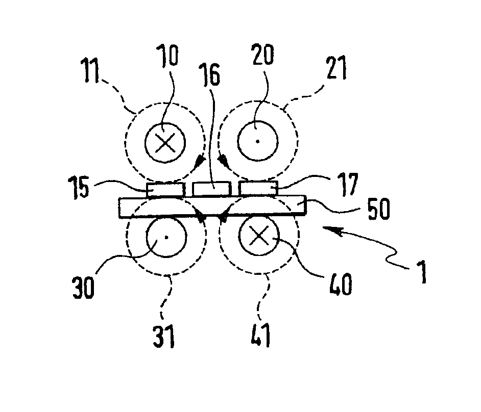
[0021]FIG. 3 shows the first embodiment of conductor 1 in the form of a cutaway view along line of intersection A-A′ from FIG. 2. First section 10 and second section 20 are visible. First section 10 and second section 20 are marked by a cross within sections 10, 20, the purpose of which is to show that the direction of flow is into the plane of the drawing. This produces magne...

second embodiment

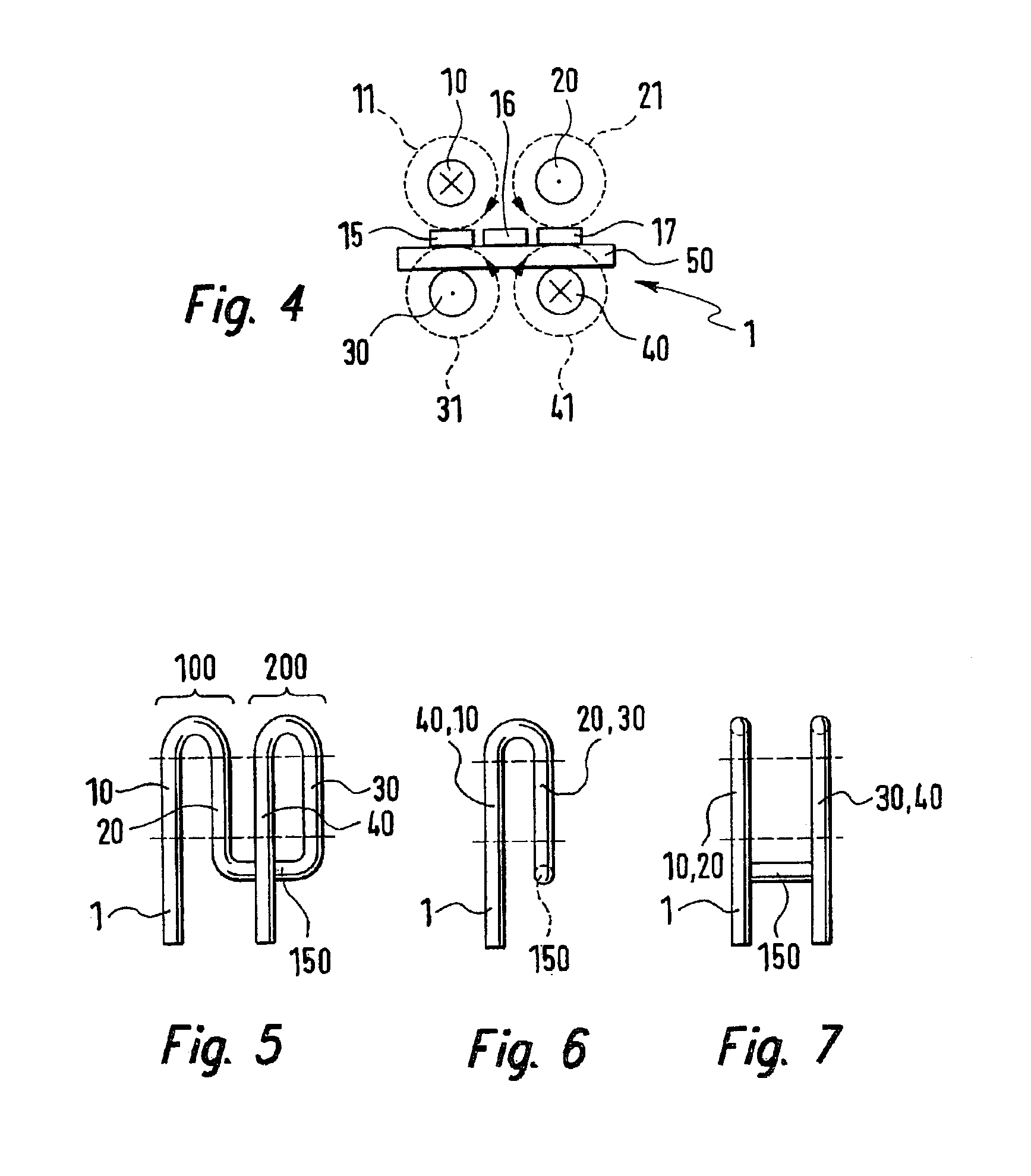
[0027]FIGS. 5, 6 and 7 show different representations of electrical conductor arrangement 1, i.e., electrical conductor 1. According to the present invention, conductor 1 includes first section 10, second section 20, third section 30 and fourth section 40. Conductor 1 also includes a first conductor area 100, which is largely in the shape of a horseshoe. First conductor area 100 includes first section 10 and second section 20. The horseshoe shape in first conductor area 100 is established as follows: First conductor area 100 includes not only first section 10 and second section 20, but also a connecting segment, which is provided more or less in the shape of a semicircle, at the ends of which first section 10 and second section 20 each form legs that continue the horseshoe shape formed by first conductor area 100. Likewise, third section 30, fourth section and an additional connecting segment of second conductor area 200 are provided in the shape of a horseshoe. The two conductor ar...


PUM


Abstract

A device, an ammeter and a motor vehicle, having a first section and a second section of a conductor for the purpose of measuring the electrical amperage in the conductor are described; a first sensor means and a second sensor means being provided; the current flowing in the first section and in the second section generating a useful magnetic field; the first sensor means being provided to measure the useful magnetic field; the second sensor means being provided in a location where the useful magnetic field disappears; the second sensor means being provided to measure a magnetic interference field; and the measurement of the useful magnetic field being correctable by the measurement of the magnetic interference field.

Description

BACKGROUND INFORMATION[0001]It is necessary in many situations to precisely detect the amperage in an at least periodically current-carrying conductor. This is done, for example, in automotive engineering to determine electrical parameters of generators and electrical drives while these units are in operation. A contactless, low-loss and potential-free measurement of the electrical current is needed for this purpose.[0002]According to the related art, shunt resistors are currently used to measure currents. Their high power loss and additional self-inductance are undesirable, especially at high amperages. In addition, they do not ensure electrical isolation between the measuring circuit and the main circuit.[0003]Magnetic field sensors, e.g., Hall sensors, lateral magnetotransistors, magnetoresistive resistors, etc., which are able to precisely measure the magnetic field effect of a current-carrying conductor, are also known. The advantage of these sensors lies, in particular, in the...

Claims


Application Information

Patent Timeline
Patent Type & Authority Patents(United States)
IPC IPC(8): G01R15/14G01R15/20G01R19/00
CPCG01R15/207
Inventor HAUENSTEIN, M. HENNINGSTRATMANN, ANDREASERNST, STEPHANFEILER, WOLFGANGNING, QU
Owner ROBERT BOSCH GMBH
Why Eureka
Try Eureka