Detecting field from different ignition coils using adjustable probe

a technology of adjustable probes and ignition coils, which is applied in the direction of spark plugs, instruments, machines/engines, etc., can solve the problems of difficult to detect the needed signal, often affecting the detection accuracy of the field, and often causing confusion

Inactive Publication Date: 2005-09-06
SNAP ON INC
View PDF10 Cites 57 Cited by
  • Summary
  • Abstract
  • Description
  • Claims
  • Application Information

AI Technical Summary

Benefits of technology

[0020]The adjustable connector may allow the signal detector to move laterally with respect to the detachable adapter when moving from the first to the second position.

Problems solved by technology

When COP technology is used, however, the coil often blocks access to the spark plug wire.
This creates a practical problem in detecting the needed signal.
Unfortunately, a single engine sometimes uses different models of COPs on its various cylinders.
This field strength differential often creates confusion during use, particularly with mechanics that are not aware of the differential.
This confusion sometimes leads to the erroneous conclusion that a particular COP is not operating properly and, in turn, to unnecessary and unfruitful repairs.

Method used


Image

  • Detecting field from different ignition coils using adjustable probe
  • Detecting field from different ignition coils using adjustable probe
  • Detecting field from different ignition coils using adjustable probe

Examples


Embodiment Construction

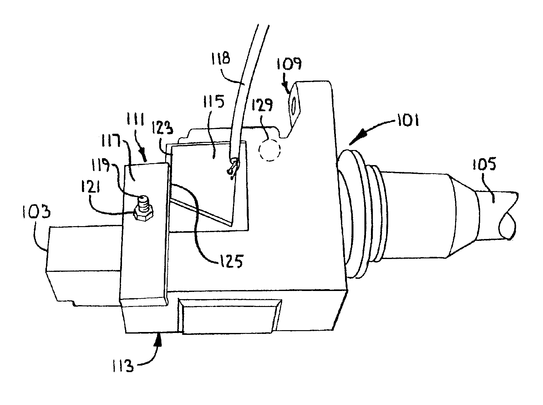
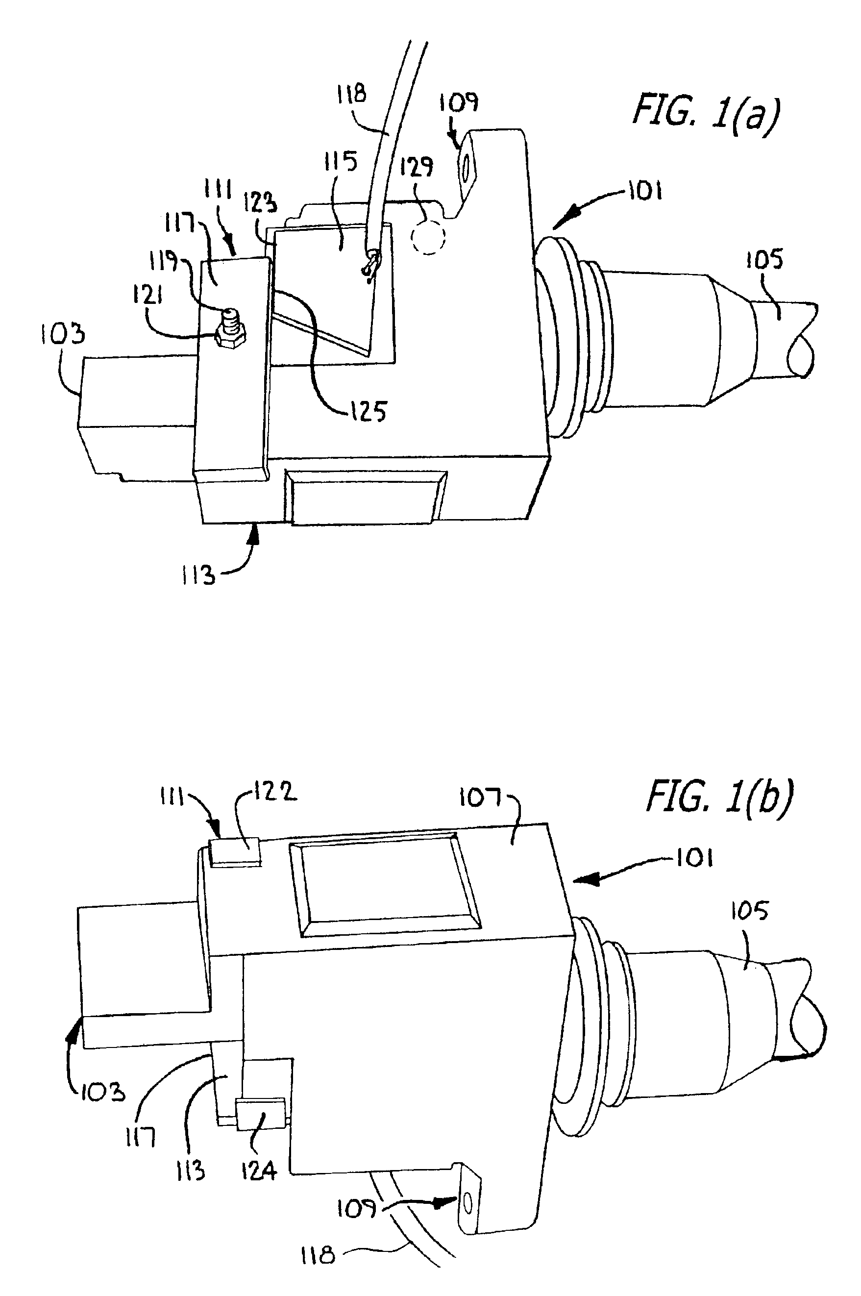
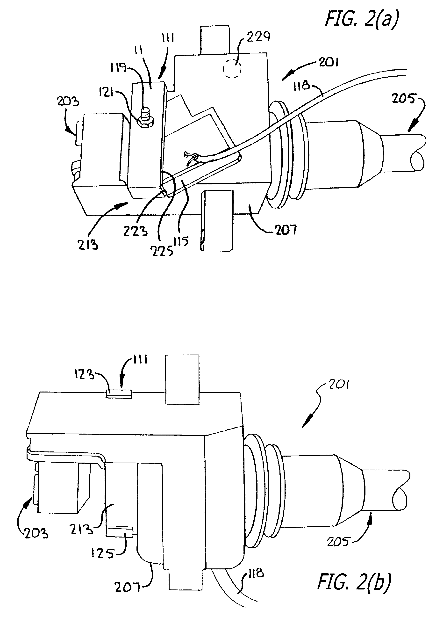
[0041]FIG. 1(a) is a perspective view of a probe for detecting a field attached to a Nissan Model 22448-2Y000 COP. FIG. 1(b) is a rear perspective view of the probe and COP shown in FIG. 1(a).

[0042]As shown in FIGS. 1(a) and 1(b), a COP 101 may include an input connector 103 into which a low input voltage is delivered. This is typically 12 volts, although different voltages levels may also be used.

[0043]The input connector 103 is sometimes configured to also receive a control signal, separate from the low input voltage. In these situations, an electronic switch (not shown) inside the COP 101 acts to deliver the low input voltage to the ignition coil when so instructed by the control signal.

[0044]In some embodiments, there is no control signal. Rather, the power signal is controlled externally and only delivered to the COP 101 when firing of the spark plug that is connected to it is desired.

[0045]The COP 101 may include an output wire 105 that is typically connected to a spark plug (...


PUM

PropertyMeasurementUnit
voltagesaaaaaaaaaa
positional displacementaaaaaaaaaa
voltageaaaaaaaaaa

Abstract

Detecting the magnetic field generated by a coil-on-plug (101) (aka coil-over-plug) using an adjustable probe (111). The probe (111) includes a signal detector (115) for detecting the field, a detachable adapter (117) configured to detachably attach to the housing (107) of the ignition coil at a specified location (113), and an adjustable connector (119 and 121) that adjustably connects the signal detector to the detachable adapter in a first predetermined position or in a second predetermined position. A detecting process and a diagnostic system using the probe are also disclosed.

Description

BACKGROUND[0001]1. Field[0002]This patent application is directed to the field of ignition coils. It is more specifically directed to measurement of the field that is emitted by ignition coils as a means of analyzing the signals that are delivered to spark plugs by the coils.[0003]2. Description of Related Art[0004]Ignition coils are commonly used to boost a low voltage supply voltage to the very high level that is necessary to ignite and sustain a spark. As is well known, the boosted voltage is usually delivered to a spark plug, typically installed in a combustion engine. The spark ignites fuel, causing increased pressure in the cylinder in which the spark plus is mounted and, in turn, movement of the engine.[0005]In the past, a single ignition coil was used to supply the high voltage needed by several spark plugs. A distributor was connected between the ignition coil and the several spark plugs to sequentially distribute the high voltage that was created by the ignition coil to ea...

Claims


Application Information

Patent Timeline
Patent Type & Authority Patents(United States)
IPC IPC(8): G01R31/38H01F5/00H01T13/60
CPCH01T13/60H01F5/003
Inventor MCQUEENEY, KENNETH A.
Owner SNAP ON INC
Why Eureka
Try Eureka