Image display device and display driving method

a display device and drive method technology, applied in the direction of electric digital data processing, instruments, computing, etc., can solve the problems of display quality deterioration, leakage of electric charge in the pixel capacitor cp, etc., and achieve the effect of improving display quality during the non-scanning period and low power consumption

Inactive Publication Date: 2005-09-06
SHARP KK
View PDF12 Cites 18 Cited by
  • Summary
  • Abstract
  • Description
  • Claims
  • Application Information

AI Technical Summary

Benefits of technology

[0013]The object of the present invention is to provide an image display device and a display driving method both of which bring about such an advantage that: display qual

Problems solved by technology

Thus, if the data signal line si is left at a potential in finishing the scanning after the scanning period, there occurs such problem that: as the source/drain voltage VDS, that is, a difference between a potential of the pixel capacitor Cp and a potential of the data signal line si is larger, a leak current occurs, so that the electric charge held in the pixel capacitor Cp may leak.
In this manner, t

Method used


Image

  • Image display device and display driving method
  • Image display device and display driving method
  • Image display device and display driving method

Examples


Embodiment Construction

[0034]One embodiment of the present invention is described as follows based on drawings.

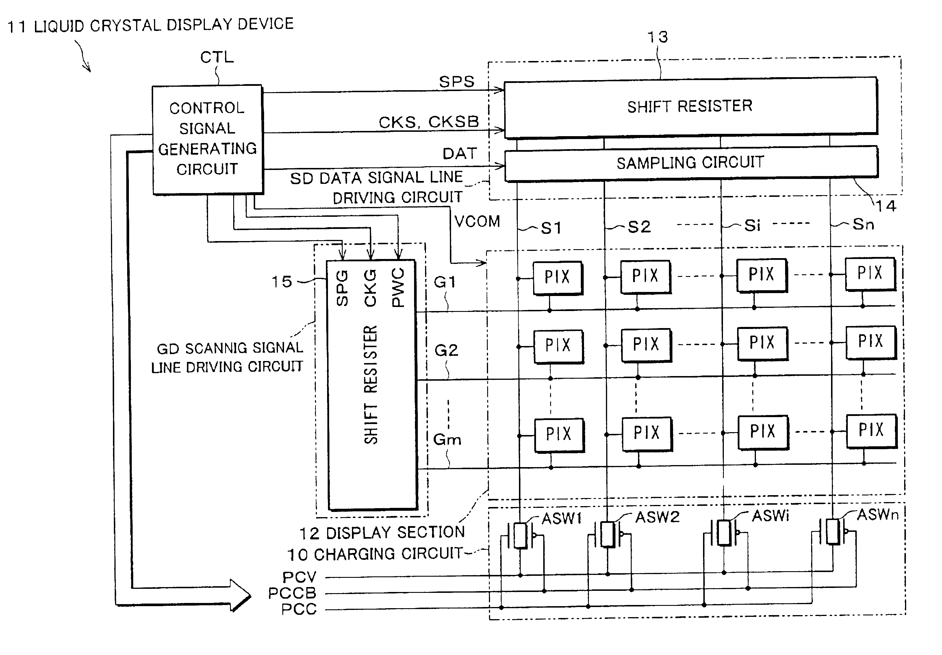
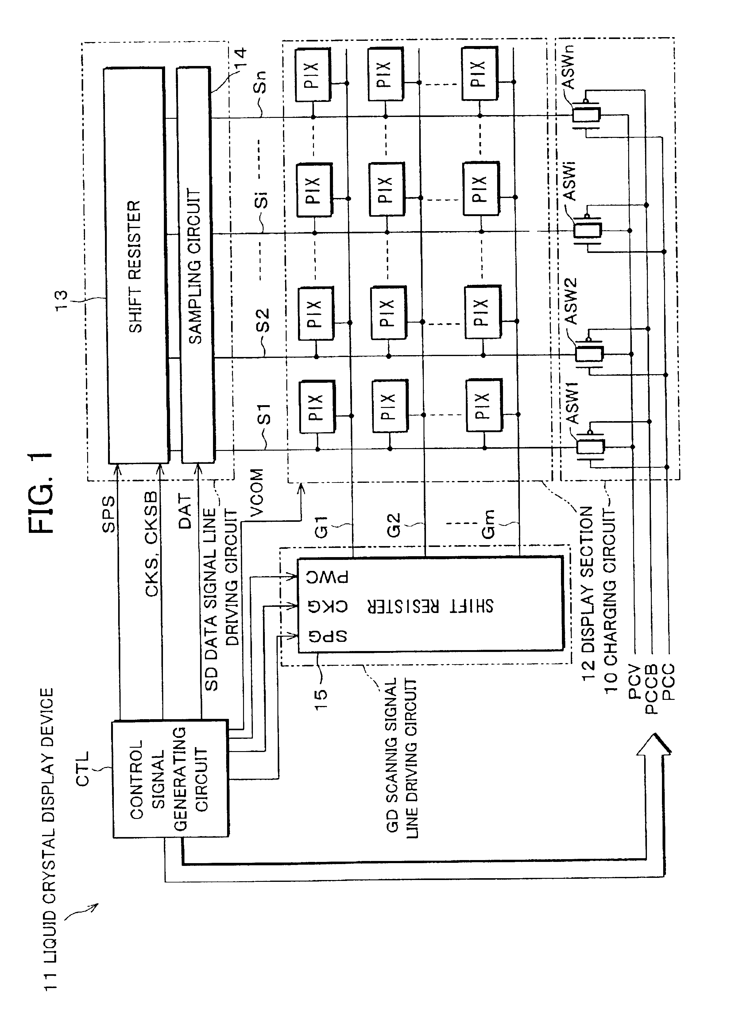
[0035]FIG. 1 is a block diagram showing an electric structure of a liquid crystal display device 11 which is an image display device of one embodiment of the present invention. The liquid crystal display device 11 is an active-matrix-type liquid crystal display device, and schematically includes: a display section 12; a scanning signal line driving circuit GD; a data signal line driving circuit SD; a charging circuit 10; and a control signal generating circuit CTL. The data signal line driving circuit SD is constituted of a shift resistor 13 and a sampling circuit 14, and the scanning signal line driving circuit GD is constituted of a shift resistor 15. The data signal line driving circuit SD and the scanning signal line driving circuit GD are arranged as in the data signal line driving circuit sd and the scanning signal line driving circuit gd in the aforementioned liquid crystal display device ...


PUM


Abstract

A potential of a data signal line S during a scanning period is charged to a substantially intermediate potential of a data signal at a corresponding frame. Thus, extremely large dispersion does not occur in a potential of each pixel capacitor with respect to a potential of the data signal line S, so that it is possible to restrict dispersion of a leak current flowing via an active element of each pixel. Thus, potential variation of a pixel PIX is reduced, so that it is possible to improve display quality during a non-scanning period. That is, in an active-matrix-type liquid crystal display, when a frame frequency is reduced by setting the non-scanning period to be sufficiently larger than a scanning period while a standby image is being displayed so as to realize low power consumption, the display quality is improved.

Description

FIELD OF THE INVENTION[0001]The present invention relates to (a) an active-matrix-type image display device, preferably realized as a liquid crystal display and the like, that includes an electro-optical element and a corresponding pair of an active element and a pixel capacitor, which are provided in each area sectored by a plurality of scanning lines and a plurality of data signal lines intersecting with each other and (b) a driving method thereof. The present invention particularly relates to an image display device and a display driving method thereof arranged so that: a frame frequency is decreased by setting a non-scanning period to be sufficiently longer than a scanning period while a standby image is being displayed, so that low power consumption is realized.BACKGROUND OF THE INVENTION[0002]FIG. 8 shows a typical active-matrix-type image display device in prior art, and gives illustration as a block diagram showing an electric structure of a liquid crystal display device 1. ...

Claims


Application Information

Patent Timeline
IPC IPC(8): G09G3/36G09G3/20G02F1/133
CPCG09G3/3648G09G3/3688G09G2310/0248G09G2330/021G09G3/36
Inventor WASHIO, HAJIMEKAISE, YASUYOSHIMAEDA, KAZUHIROKUBOTA, YASUSHI
Owner SHARP KK
Why Eureka
Try Eureka