Flash tank economizer refrigeration systems

a technology of economizer refrigeration system and flash tank, which is applied in the direction of refrigerating machines, fluid circulation arrangement, lighting and heating apparatus, etc., can solve the problems of complex arrangement of flash tank, complex arrangement of internal baffles, etc., to improve the operation and performance of a compression refrigeration system, simple construction, and reliable and efficient operation

Inactive Publication Date: 2005-09-13
YORK INT CORP
View PDF17 Cites 39 Cited by
  • Summary
  • Abstract
  • Description
  • Claims
  • Application Information

AI Technical Summary

Benefits of technology

[0010]One advantage of the present invention is improved operation and performance of a compression refrigeration system.
[0011]Another advantage of the present invention is that it has a simple construction that can operate reliably and efficiently in a refrigeration system, and yet is inexpensive and simple to construct and install in a compression refrigeration system having an economizer circuit.
[0012]Still another advantage of the present invention is that it provides efficient expansion of the high-pressure refrigerant moving between the condenser and the evaporator of a compression refrigeration system.

Problems solved by technology

Known flash tanks for use in economizer circuits are relatively complex structures.
For example, known flash tanks have complex arrangements of internal baffles, floats, phase separation screens, and other components.
Such complex arrangements are expensive and time-consuming to manufacture, maintain, and repair.

Method used


Image

  • Flash tank economizer refrigeration systems
  • Flash tank economizer refrigeration systems
  • Flash tank economizer refrigeration systems

Examples


Embodiment Construction

[0026]The subject matter of the invention under consideration is directed to a system and process for improving the efficiency and capacity of a refrigeration system employing an economizer. The system and process can be used with any type of compressor, but is particularly suited for use with screw compressors, since screw compressors can easily incorporate economizers.

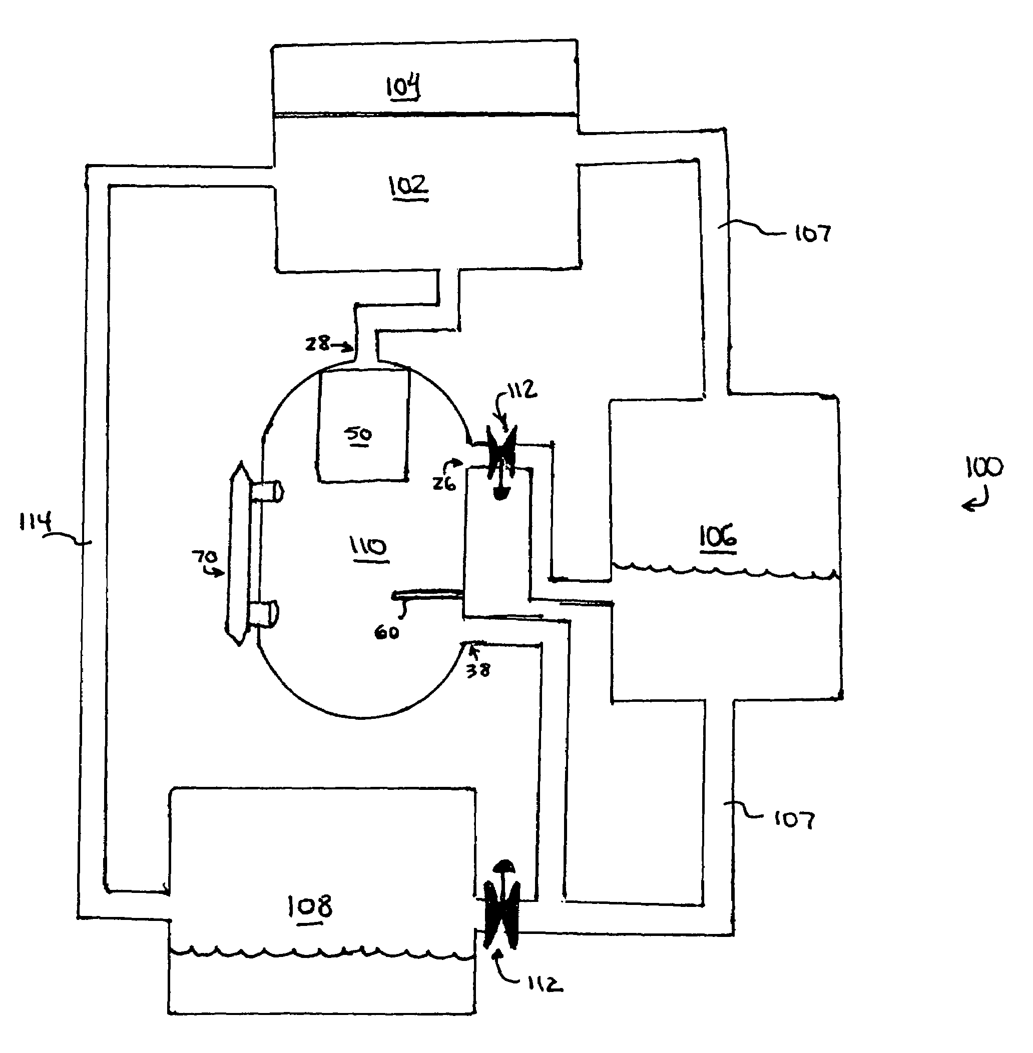
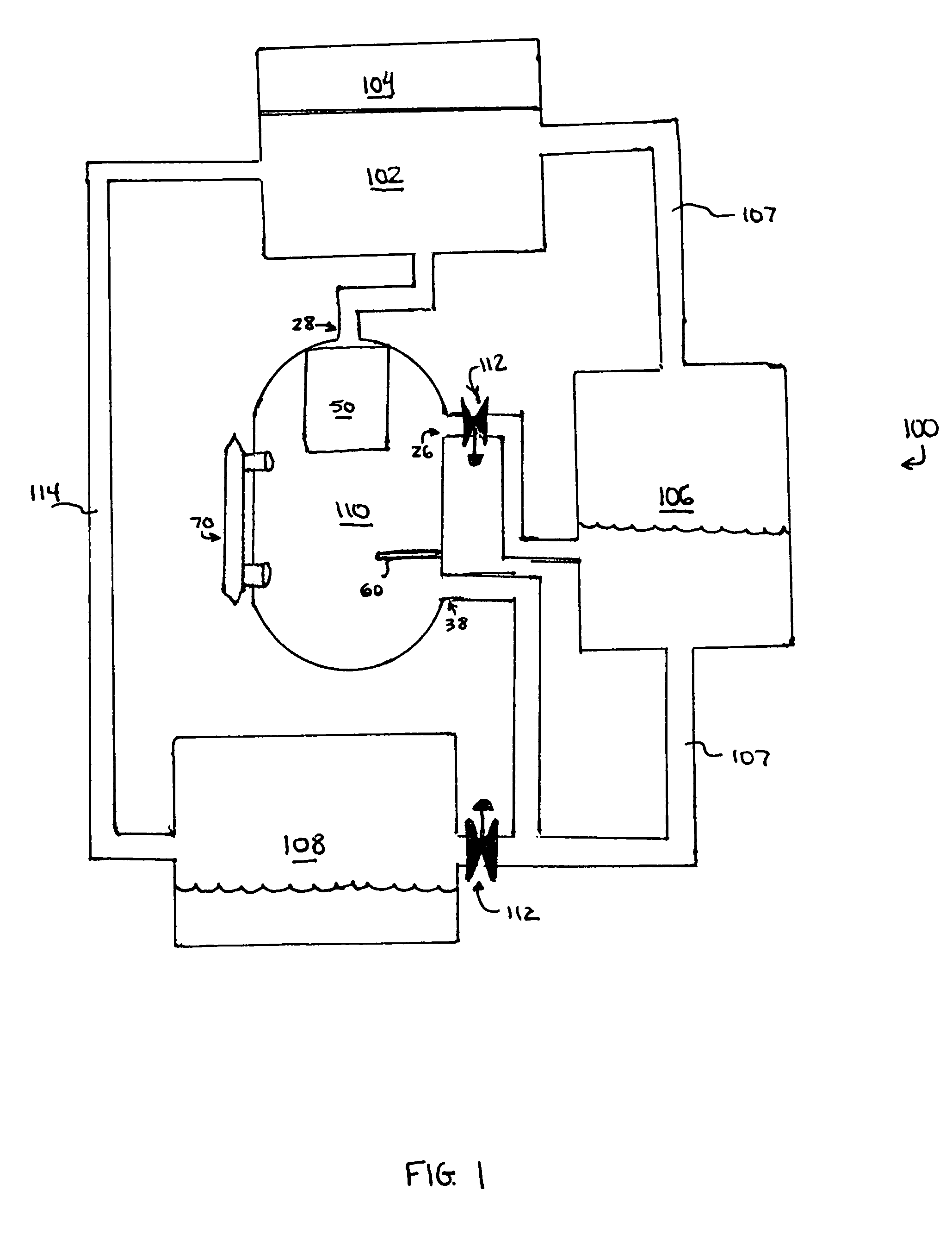
[0027]Referring initially to FIG. 1, there is shown a conventional refrigeration system 100 incorporating an economizer circuit in accordance with the present invention. As shown, refrigeration system 100 includes a compressor 102, a motor 104, a condenser 106, an evaporator 108, and an economizer flash tank 110. The conventional refrigeration system 100 includes many other features that are not shown in FIG. 1. These features have been purposely omitted to simplify the drawing for ease of illustration.

[0028]Compressor 102 compresses a refrigerant vapor and delivers the vapor to the condenser 106 through a discharge ...


PUM


Abstract

A flash tank configuration for an economizer is provided that is inexpensive and simple to construct, reliable to operate, and efficient for use in an economizer compression refrigeration system. The configuration includes an upper baffle and a lower baffle configured and arranged within the flash tank so as to separate the liquid and gas phases of intermediate pressure refrigerant, and to convey each phase to other components in the refrigeration systems. The flash tank has a generally cylindrical shape, and is dimensioned so as to provide adequate internal volume for expansion of refrigerant to a desired pressure, separation of the resulting refrigerant gas and refrigerant liquid phases, and temporary storage of the refrigerant phases before conveying the liquid phase to the main refrigerant line between the condenser and the evaporator, and returning the gas phase to the compressor. Additionally, methods are provided for using the flash tank to separate refrigerant phases.

Description

BACKGROUND OF THE INVENTION[0001]This invention relates to capacity and efficiency control of refrigeration systems, and in particular, to a flash tank economizer for enhancing the performance of a refrigeration system. As will be explained below, the present invention involves a novel configuration of a flash tank economizer configuration that utilizes a system of internal baffles to produce expansion of refrigerant liquid, separation of the resulting refrigerant gas from the remaining refrigerant liquid, and temporary storage of both the refrigerant gas and liquid before conveying them to other components of the refrigeration system.[0002]A typical compression refrigeration system is composed of the following components: an evaporator for exchanging heat between a medium to be cooled and a refrigerant; a compressor that takes the low-pressure gas refrigerant generated in the evaporator and compresses the gas to a suitable higher pressure; a condenser that facilitates the heat exch...

Claims


Application Information

Patent Timeline
Patent Type & Authority Patents(United States)
IPC IPC(8): F25B43/00F25B1/047F25B1/04F25B1/10
CPCF25B43/00F25B1/047F25B1/10F25B2700/04F25B2400/16F25B2400/23F25B2400/13F25B1/04
Inventor HILL, IV, FRANK HIGHLANDCRANE, CURTIS CHRISTIANBUCKLEY, MICHAEL LEESTABLEY, BLAKE EVAN
Owner YORK INT CORP
Why Eureka
Try Eureka