Gravity type tiltable metal mold casting machine

a metal mold and casting machine technology, applied in the direction of molten metal supply equipment, manufacturing tools, melt-holding vessels, etc., can solve the problems of inherently long devices located below the drag, the extended tilting stroke of the machine, and the inability to adjust the tilting strok

Inactive Publication Date: 2005-09-13
SINTOKOGIO LTD
View PDF4 Cites 12 Cited by
  • Summary
  • Abstract
  • Description
  • Claims
  • Application Information

AI Technical Summary

Benefits of technology

[0006]To the above end, the gravity type tiltable metal mold casting machine of the present invention includes a pair of opposing upright supporting frames; a pair of opposing main rotating shafts disposed on an axis of rotation and rotatably mounted on the upper ends of the upright supporting frames; a main frame fixedly mounted on the rotating shafts such that it is suspended from and between them; a drag die plate moved vertically by mold-fastening cylinders mounted on a lower part of the main frame; a metal drag secured to the drag die plate, the metal drag having a drag pushing-out mechanism for pushing an as-cast product out of the metal drag; a pair of opposing cope tilting shafts horizontally disposed on a horizontal axis and secured to an upper end of the main frame at locations rearward of the main rotating shafts; a cope-attaching frame rotatably mounted at one end on the cope tilting shafts; a cope die plate secured to a lower surface of the cope-attaching frame; and a metal cope secured to the cope die plate, the metal cope having a cope pushing-out mechanism for pushing an as-cast product out of the metal cope, wherein the center of the metal cope and drag assembly is substantially on the axis of rotation of the main rotating shafts.

Problems solved by technology

Thus, when the molds are tilted and molten metal is poured into them, the center of the mold assembly rotates at a location away from the axis of rotation, thereby exerting great rotatory inertia to the molten metal flowing in the molds.
This molten metal flowing in the mold assembly with the great rotatory inertia tends to swirl and thus tends to convolute the air, thus producing oxide films, and tends to convolute the films.
This causes a problem in that the period of the tilting stroke of the machine must be prolonged.
Further, due to the limitation in minimizing the tilting radius of the machine, and since a cylinder for lowering the cope as well as for fastening the cope and the drag and a cylinder for actuating a mechanism for pushing out an as-cast product are aligned, devices located below the drag are inherently long, and the machine inherently has a great tilting radius (i.e., a great rotatory inertia).
Further, there is another problem in that the height from the surface on which the machine is installed to the metal drag is great.
This makes difficult the operations of putting cores in the drag and taking out an as-cast product.

Method used


Image

  • Gravity type tiltable metal mold casting machine
  • Gravity type tiltable metal mold casting machine
  • Gravity type tiltable metal mold casting machine

Examples


Embodiment Construction

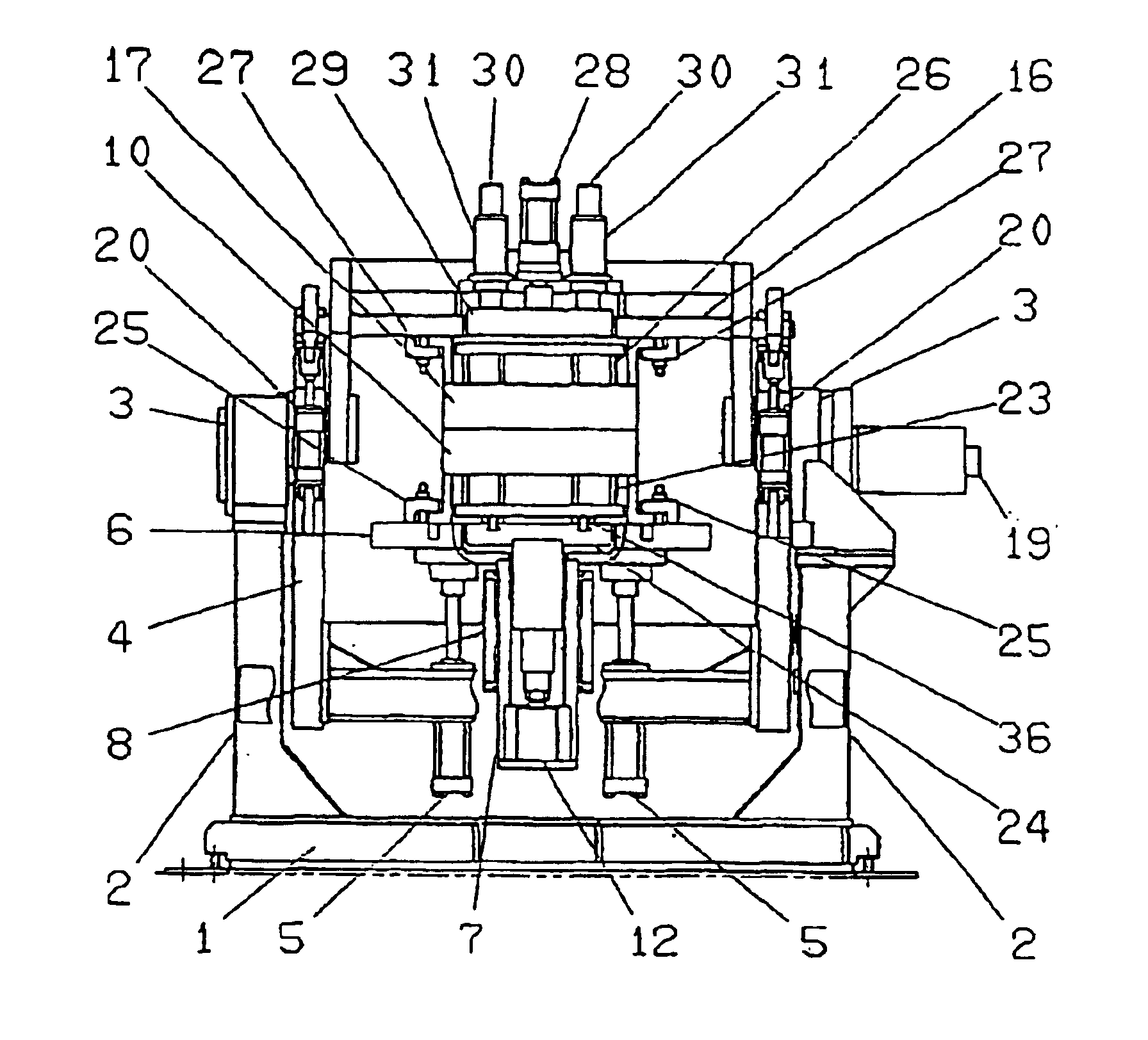
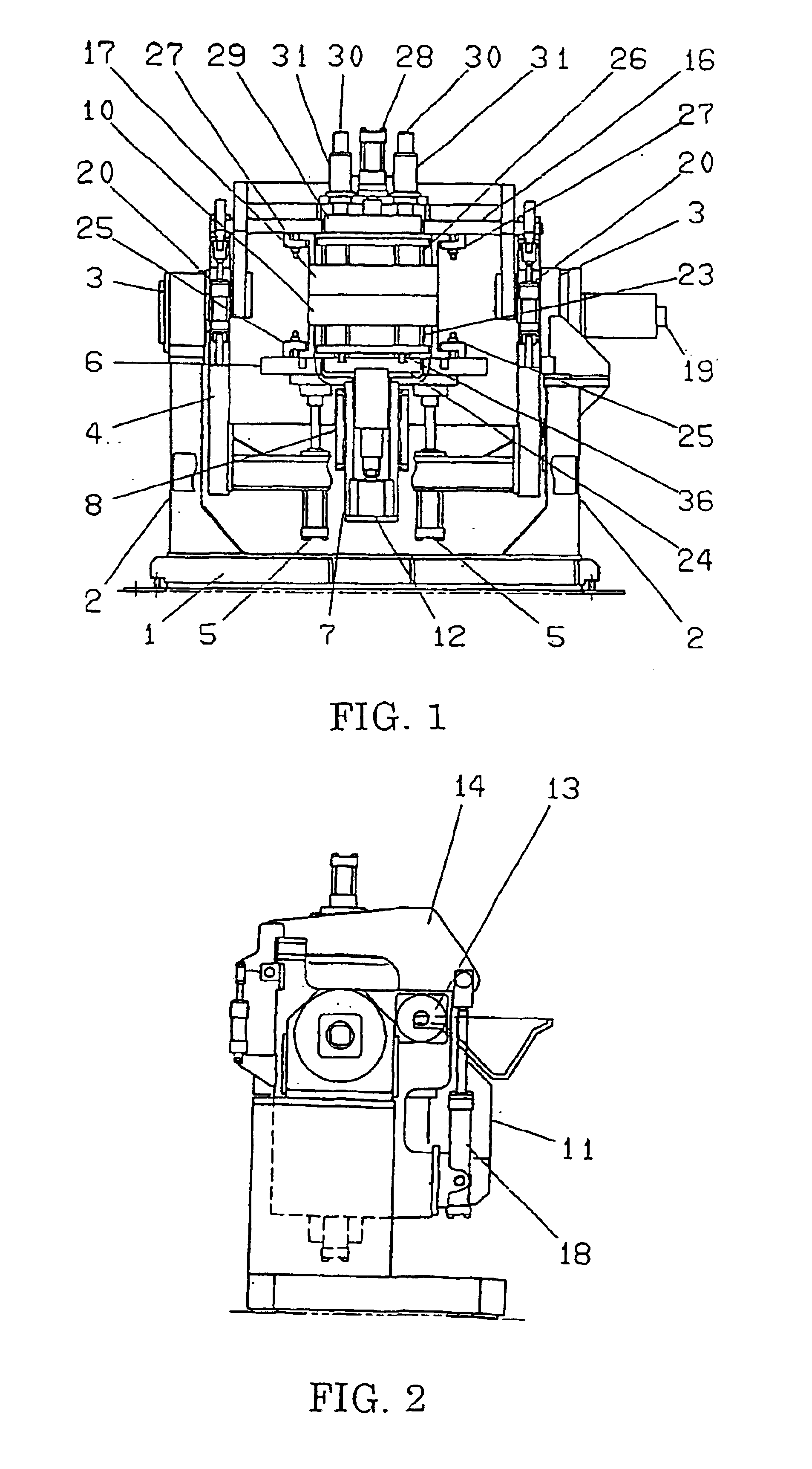
[0022]Below the embodiment of the present invention is explained in detail by reference to the accompanying drawings. In FIGS. 1 and 2 a pair of opposing upright frames 2, 2 are mounted on a base 1. A pair of opposing main rotating shafts 3, 3 are disposed on an axis and rotatably mounted on the upper ends of the upright frames 2, 2. A main frame 4 is fixedly mounted on the main rotating shafts 3, 3 such that it is suspended from and between them. For reversibly rotating the main frame 4A, a main electric motor 19, such as a servomotor, is mounted on one of the supporting frames 2, 2. The output shaft of the main electric motor 19 for reversibly rotating the main frame 4 is connected to one end of one of the main rotating shafts 3, 3.

[0023]A plurality of upwardly-facing cylinders 5, 5, for fastening the molds, are mounted on a lower part of the main frame 4. A drag die plate 6 is secured to the distal ends of the piston rods of the mold-fastening cylinders 5, 5. A hollow guide rod 7...


PUM

PropertyMeasurementUnit
gravityaaaaaaaaaa
axis of rotationaaaaaaaaaa
rotationaaaaaaaaaa

Abstract

A gravity type tiltable metal mold casting machine, comprising: a pair of opposing upright supporting frames (2, 2); a pair of opposing main rotating shafts (3, 3) rotatably mounted on the upright supporting frames (2, 2); a main frame (4) suspended from and between the main rotating shafts (3, 3); an electric motor (19) attached to one of the main rotating shafts (3, 3) for reversibly rotating it and hence the frame (4); a drag die plate (6) vertically moved by mold-fastening cylinders (5, 5) mounted on a lower part of the main frame (4); a metal drag (10) secured to the drag die plate (6), the metal drag having a drag pushing-out mechanism (23) for pushing an as-cast product out of the metal drag; a pair of opposing horizontal cope tilting shafts (13, 13) secured to an upper end of the main frame at locations rearward of the main rotating shafts (3, 3); a cope-attaching frame (14) rotatably mounted at one end on the cope tilting shafts (13, 13); a cope die plate (16) secured to a lower surface of the cope-attaching frame (14); a metal cope (17) secured to the cope die plate (16), the metal cope having a cope pushing-out mechanism (26) for pushing an as-cast product out of the metal cope, a ladle (21) rotatably mounted about a horizontal axis of rotation, the horizontal axis of rotation being located rearward of the assembly of the metal cope and drag; and an electric motor (9) for reversibly rotating the ladle (21) about the horizontal axis of rotation, wherein the center of the assembly of the metal cope and drag is substantially on the axis of rotation of the main rotating shafts.

Description

FIELD OF THE INVENTION[0001]This invention relates to a gravity type tiltable metal mold casting machine wherein molten metal (for example, aluminum) is poured into a mold cavity formed by a metal cope and a metal drag while they are being tilted.DESCRIPTION OF THE PRIOR ART[0002]Such a conventional gravity type tiltable metal mold casting machine is disclosed in JP H5-318090A. This machine is configured such that both the rotation of the entire casting machine and the rotation of the metal cope (i.e., releasing the upper opening of the metal drag) are performed around a common axis (an axis of rotation located outside the metal cope and drag assembly).[0003]Since in this machine the axis of rotation of the machine and the axis of rotation of the metal cope are the same, the single axis of rotation must be located outside the metal cope and drag assembly so as to make the upper part of the drag be completely open when the metal cope is opened. Thus, when the molds are tilted and mol...

Claims


Application Information

Patent Timeline
Patent Type & Authority Patents(United States)
IPC IPC(8): B22D23/00
CPCB22D23/006
Inventor OSUGI, MITSUHARUNARUSE, EIJIKANAYAMA, YUJIMURATA, YUTAKA
Owner SINTOKOGIO LTD
Why Eureka
Try Eureka