AI technical title is built by Patsnap AI team. It summarizes the technical point description of the patent document.
a microchannel cooling and electroosmotic technology, applied in the direction of fluid speed measurement, insulated cables, conductors, etc., can solve the problems of reducing the volume and surface area available for cooling devices, significant excess heat is added, and conventional heat sinks are simply incapable of removing the targeted power and power densities within a volume, so as to minimize the spatial and temporal temperature variations of the device, minimize the shape and distribution of the microchannel, and minimize the effect of device temperature variation
Inactive Publication Date: 2005-09-13
THE BOARD OF TRUSTEES OF THE LELAND STANFORD JUNIOR UNIV
View PDF175 Cites 244 Cited by
Summary
Abstract
Description
Claims
Application Information
AI Technical Summary
This helps you quickly interpret patents by identifying the three key elements:
Problems solved by technology
Method used
Benefits of technology
Benefits of technology
[0021]The present invention has the capability of removing high heat fluxes and high total power from devices.
[0028]Apparatus and methods according to the present invention also allow active regulation of the temperature of the device through electrical control of the flow through the pump and can utilize multiple cooling loops to allow independent regulation of the special and temporal characteristics of the device temperature profiles.
Problems solved by technology
Conventional heat sinks are simply incapable of removing the targeted powers and power densities within a volume consistent with system design and market expectations.
This situation is exacerbated by targeted reductions of total system volume, which diminish the volume and surface area available for cooling devices.
The interaction of these two trends (increasing head load and decreasing system volume) are recognized as a critical problem for the future of the semiconductor industry, and for other industries that rely on heat-generating or absorbing devices.
In these applications, the heat from the device is transported to the rejection surface, and significant excess heat is added due to the limited thermodynamic efficiency of the cooling mechanism.
Cooling water is used in situations where large quantities of heat are generated, and the other methods described herein are unable to reject the heat to the surrounding air.
These pumps, to date, appear to be incapable of generating the pressure and / or flow necessary for application to removal of high heat flux from high-power devices.
These issues tend to be prominent in closed-loop fluidic cooling systems employing pumps.
Method used
Image
Click on the blue label to locate the original text in one second.
Reading with bidirectional positioning of images and text.
Examples
Embodiment Construction
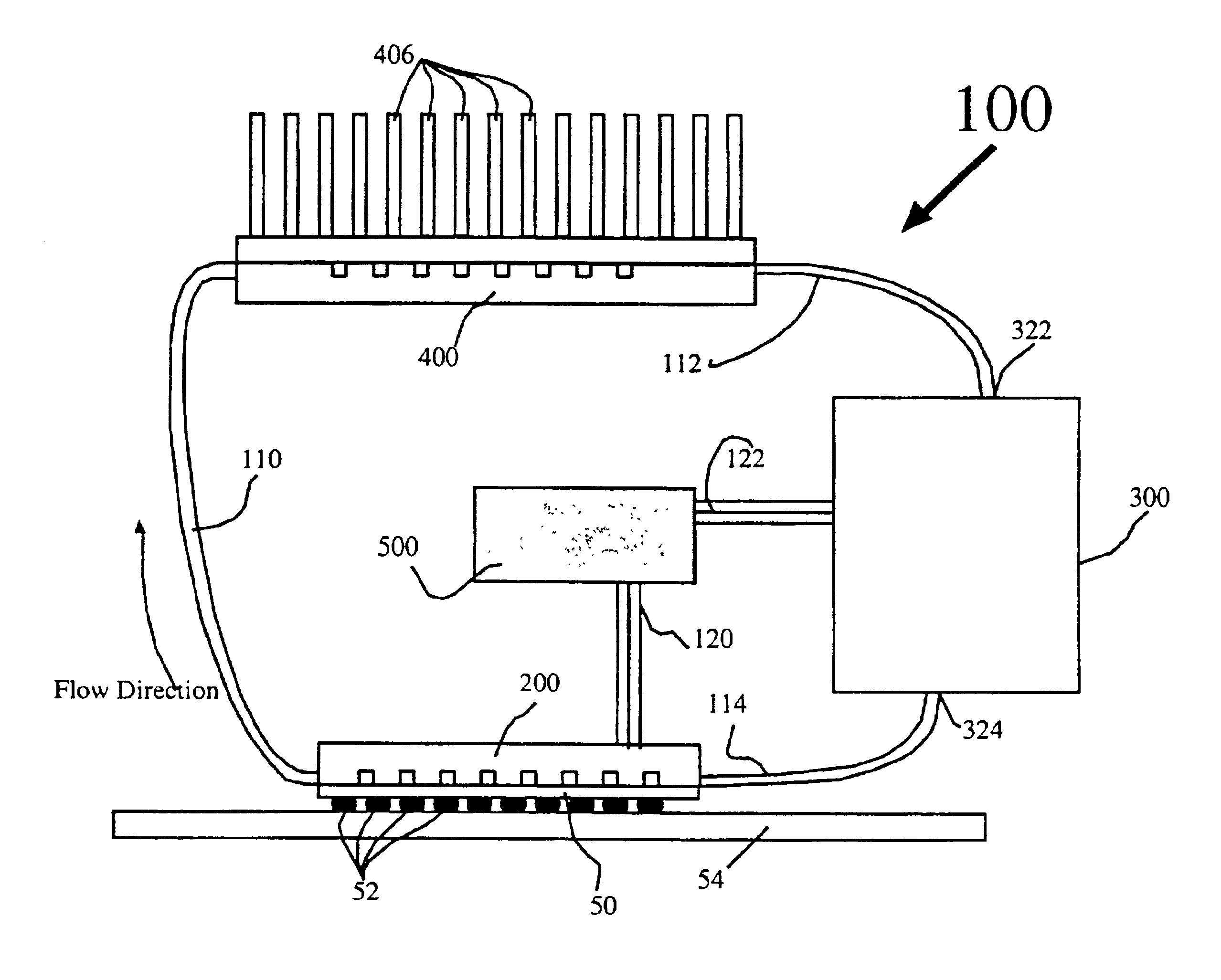
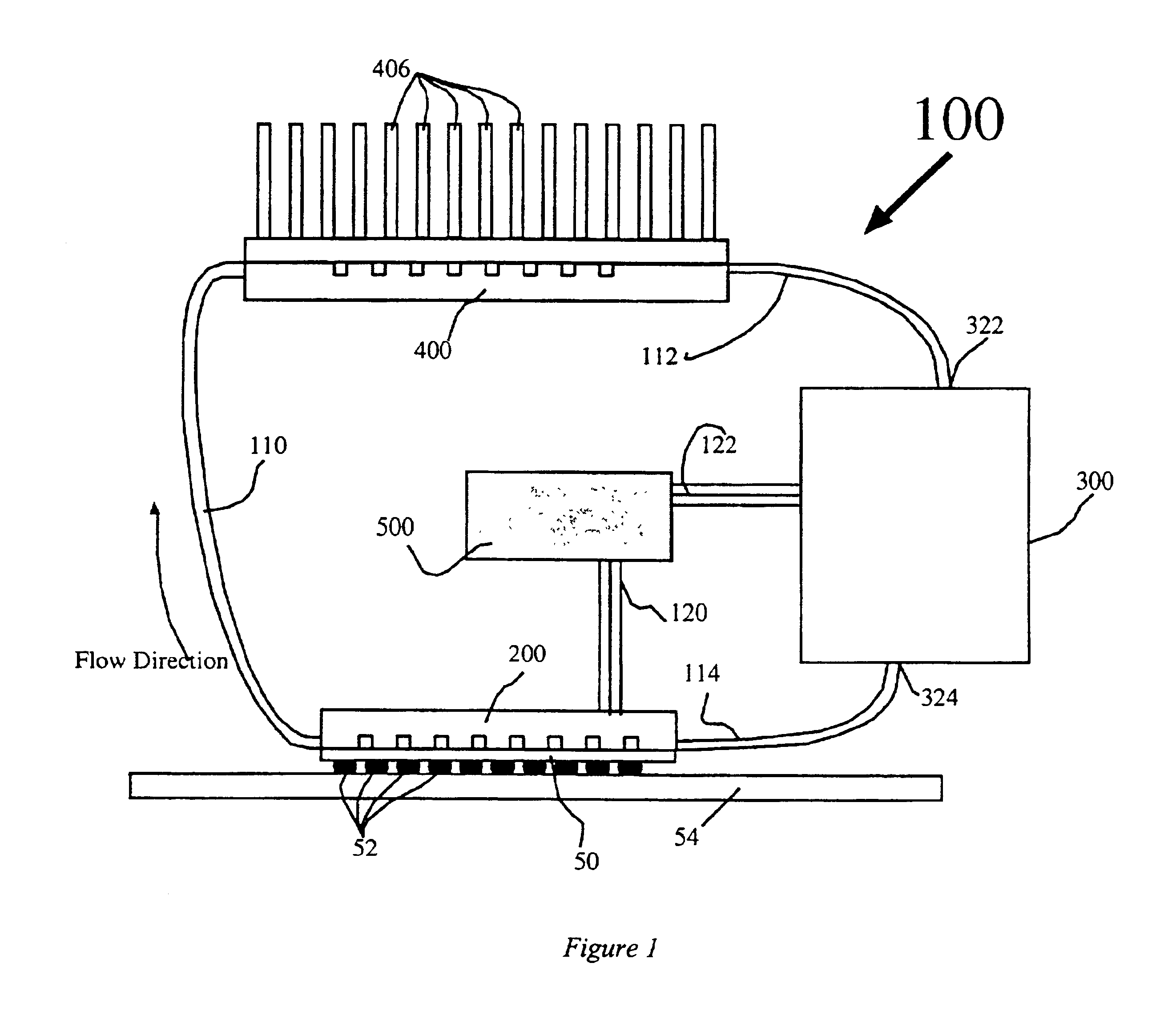
[0070]The present invention provides, in one aspect, a compact cooling system for electronic systems based on micro heat exchangers, specifically microchannels machined in silicon or metals, and compact electroosmotic pumps. The system is hermetically-closed and may be arranged in a modular fashion, enabling efficient heat removal from a device, and transport to a convenient macro heat exchanger. The micro heat exchangers and electroosmotic pumps as described are extremely compact and power-efficient, such that the total system is far smaller and lighter than heat pipes, vapor chambers, and fin-array heat sinks usually used for removing comparable power from miniature devices. The system is interconnected by flexible tubing and therefore offers advantages in design flexibility. Certain embodiments of the system are generally referred to as the loop system since in its preferred form the various components establish a closed-loop through which the liquid that provides for thermal ene...
PUM
Abstract
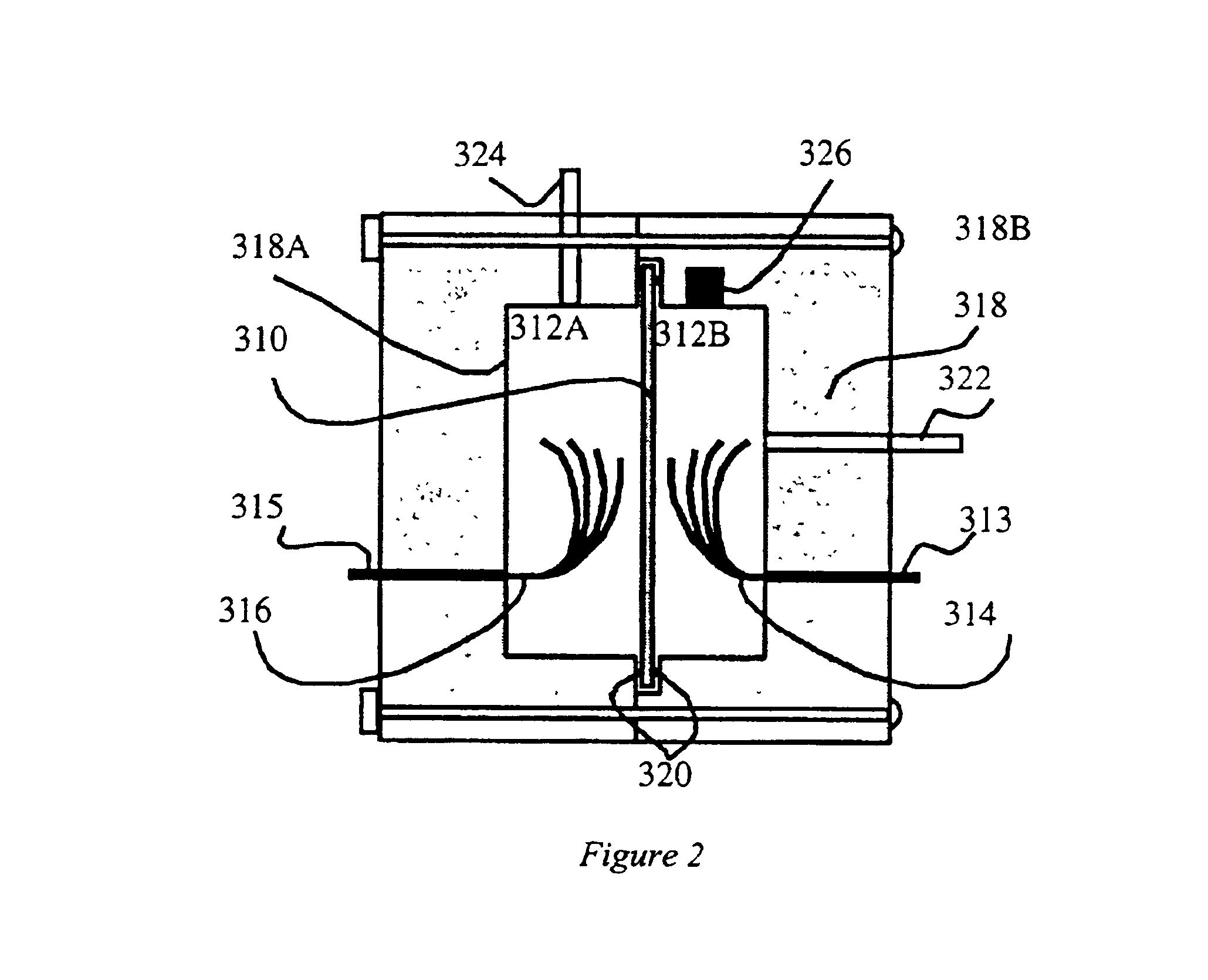
Apparatus and methods according to the present invention preferably utilize electroosmotic pumps that are capable of generating high pressure and flow without moving mechanical parts and the associated generation of unacceptable electrical and acoustic noise, as well as the associated reduction in reliability. These electroosmotic pumps are preferably fabricated with materials and structures that improve performance, efficiency, and reduce weight and manufacturing cost relative to presently available micropumps. These electroosmotic pumps also preferably allow for recapture of evolved gases and deposited materials, which may provide for long-term closed-loop operation. Apparatus and methods according to the present invention also allow active regulation of the temperature of the device through electrical control of the flow through the pump and can utilize multiple cooling loops to allow independent regulation of the special and temporal characteristics of the device temperature profiles. Novel microchannel structures are also described.
Description
[0001]This application is related to, claims priority of and expressly incorporates by reference herein U.S. application No. 60 / 326,151 filed Sep. 28, 2001. The inventions described herein were supported in part by DARPA / Air Force Contract F33615-99-C-1442.FIELD OF THE INVENTION[0002]This invention relates generally to removal of heat from heat generating devices. Specifically, this invention relates to removal of heat from integrated circuits, opto-electronic devices, power electronics, bioanalytical devices and any devices that dissipate or absorb sufficient heat so as to require specific means for heat removal.BACKGROUND OF THE INVENTION[0003]Electronic systems, including, for example, laptop, hand-held and desktop computers as well as cell phones operate through the use of input electrical power. These have the characteristic that some of the input power is converted to heat, and the heat generated is typically concentrated in an identifiable area, such as an integrated circuit ...
Claims
Application Information
Patent Timeline
Application Date:The date an application was filed.
Publication Date:The date a patent or application was officially published.
First Publication Date:The earliest publication date of a patent with the same application number.
Issue Date:Publication date of the patent grant document.
PCT Entry Date:The Entry date of PCT National Phase.
Estimated Expiry Date:The statutory expiry date of a patent right according to the Patent Law, and it is the longest term of protection that the patent right can achieve without the termination of the patent right due to other reasons(Term extension factor has been taken into account ).
Invalid Date:Actual expiry date is based on effective date or publication date of legal transaction data of invalid patent.
InventorGOODSON, KENNETH E.CHEN, CHUAN-HUAHUBER, DAVID E.JIANG, LINANKENNY, THOMAS W.KOO, JAE-MOLASER, DANIEL J.MIKKELSEN, JAMES C.SANTIAGO, JUAN G.WANG, EVELYN NING-YIZENG, SHULINZHANG, LIAN
OwnerTHE BOARD OF TRUSTEES OF THE LELAND STANFORD JUNIOR UNIV

