Locator tab and associated hose clamp

a technology of hose clamps and tabs, which is applied in the direction of hose connections, transportation and packaging, and other domestic objects, can solve the problems of preventing the clamp from achieving adequate sealing, lack of surface area, and insufficient strength of the clamp, so as to reduce the bending resistance and resist substantial pull-off loads

Inactive Publication Date: 2005-09-13
EPICOR IND
View PDF11 Cites 36 Cited by
  • Summary
  • Abstract
  • Description
  • Claims
  • Application Information

AI Technical Summary

Benefits of technology

[0004]Accordingly, it is an aspect of the present invention to provide an improved locator and clamp configuration that is able to statically position a hose clamp in a predetermined radial orientation, and in close proximity to the end of a hose, and resist substantial pull off loads. The improved hose clamp locator comprises a connection portion, a head portion, a deflecting portion having a reduced bending resistance positioned between the connection and head portion, an end portion extending angularly from the head portion, a clip portion extending angularly from the end portion, and a tooth portion disposed to engage an interior surface of a hose extending angularly from the clip portion.

Problems solved by technology

At such a close proximity to the end of a hose, the rigidity of the hose is substantially lower, thereby creating problems with locators that rely on such rigidity, as the hose tends to “cave in” when exposed to an inward radial pressure, such as from spring liners and plastic retainers.
The use of adhesive to locate a clamp in such situations has also proven unsatisfactory for many reasons, including the lack of sufficient surface area to provide an adequate bond.
Additionally, adjusting the length of standard clip configurations has created problems in that the rigidity of the clips has conflicted with and prevented the clamps from achieving adequate sealing.
As the clamp has been tightened in such configurations, the rigidity and length of the locator clip has actually interfered with the clamp itself.
This has caused the locator to undesirably deflect the clamp outwardly and separate the hose from the fitting.

Method used


Image

  • Locator tab and associated hose clamp
  • Locator tab and associated hose clamp
  • Locator tab and associated hose clamp

Examples


Embodiment Construction

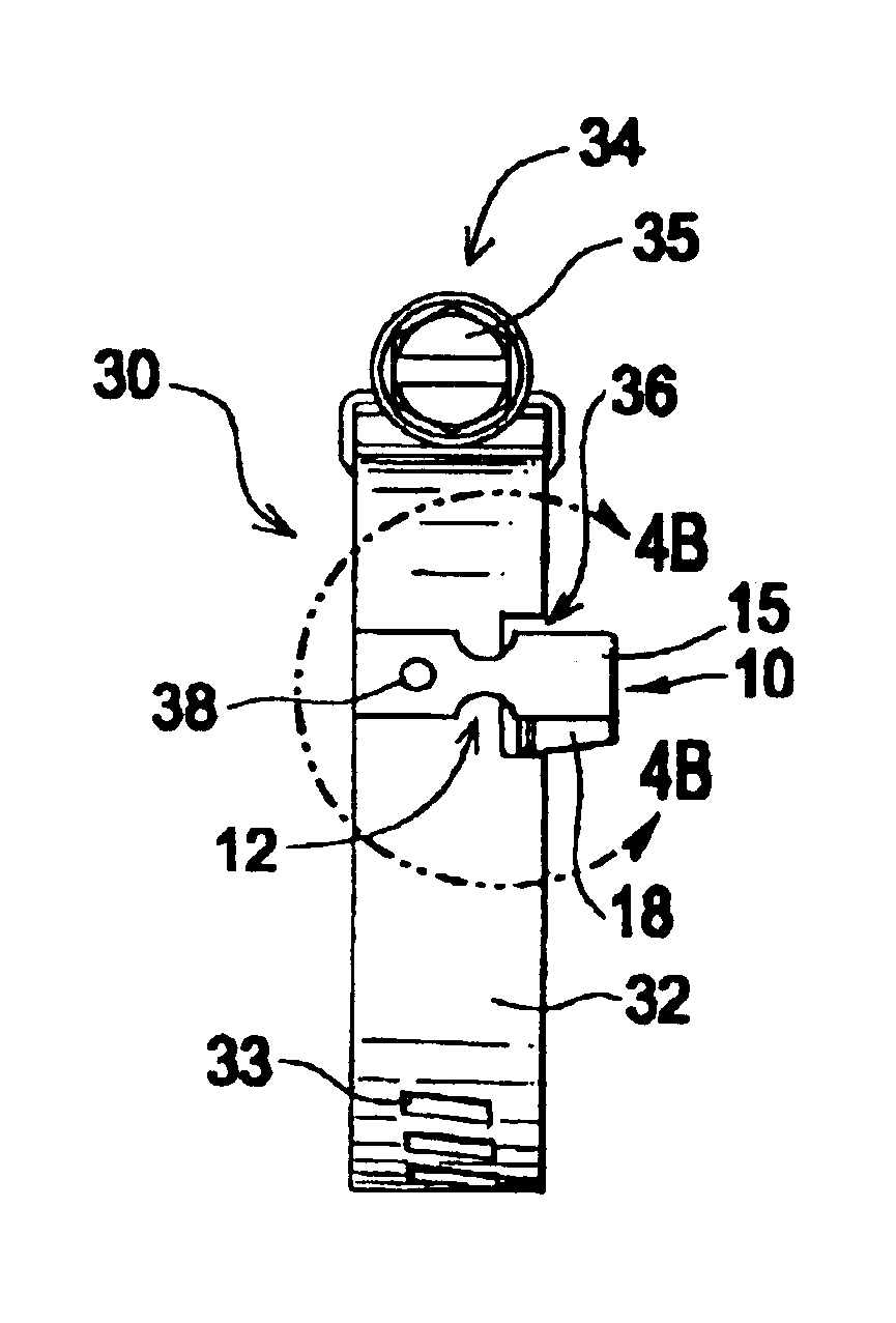
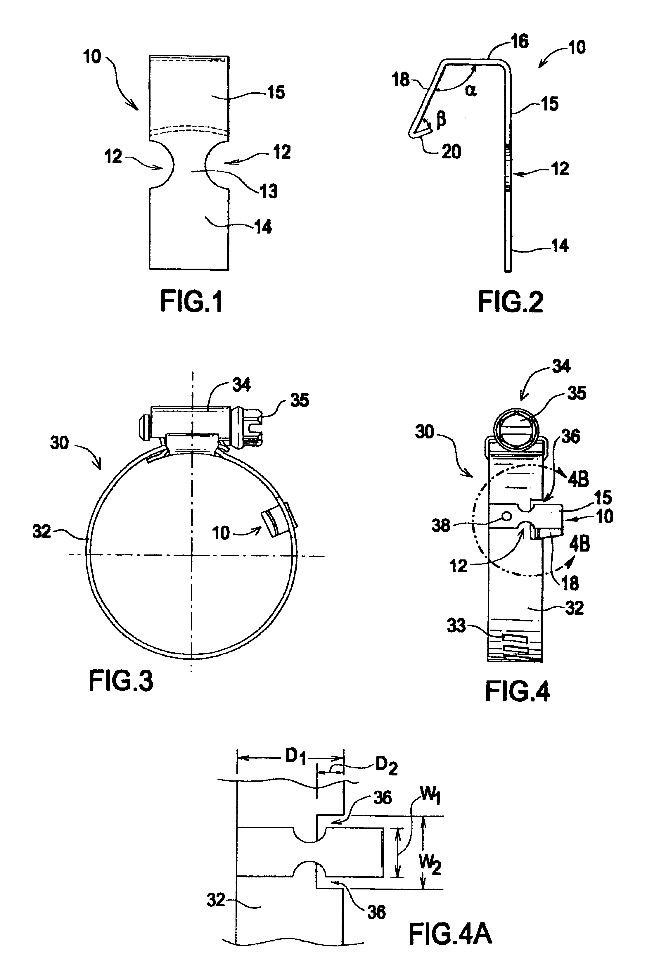
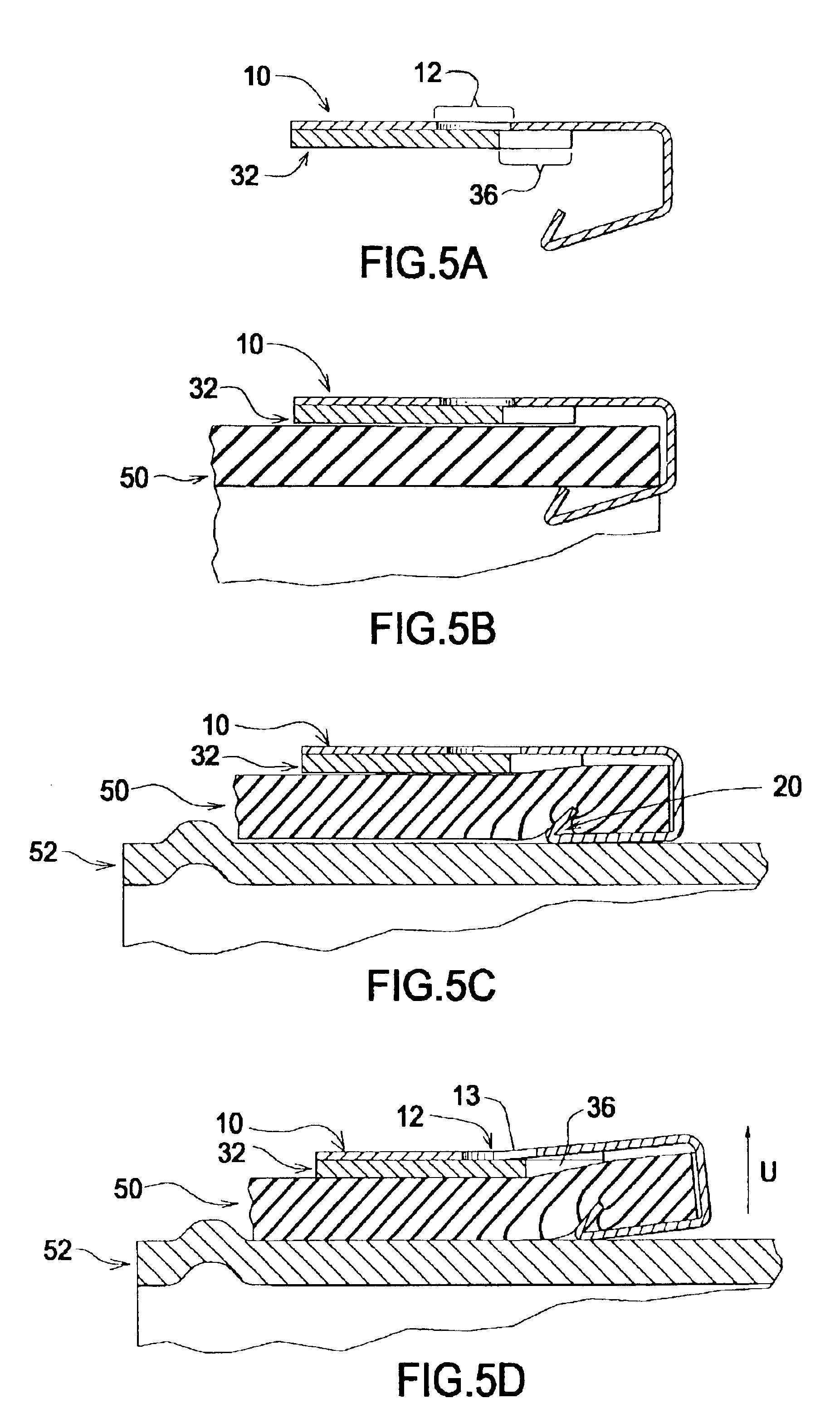
[0017]Referring to FIG. 1, a clamp locator (shown generally at 10) is comprised of a connection portion 14, deflecting portion 13, and head portion 15. Connection portion 14 is disposed to be connectable to a hose clamp, so it is preferable that it is substantially planar or slightly rounded to match the radial shape of the hose clamp. The deflecting portion 13 is located between the connection portion 14 and head portion 15, and may be generally shaped by partial apertures 12. The deflecting portion 13 shall have a generally reduced bending resistance compared to the head portion 15, in order to facilitate deflection under hose tightening operations, as is discussed in more detail below.

[0018]The partial apertures 12 illustrated in FIG. 1 are shown as two semi-circle cutouts located at the edges. The purpose of the apertures is to sufficiently degrade the rigidity of the overall clamp locator 10 to allow it to deflect under loads caused by the tightening of an associated hose clamp...


PUM

PropertyMeasurementUnit
angleaaaaaaaaaa
angleaaaaaaaaaa
angleaaaaaaaaaa

Abstract

An improved locator and hose clamp configuration that is able to statically position a hose clamp in close proximity to the end of a hose, and resist substantial pull off loads. The improved hose clamp locator comprises a connection portion, a head portion, a deflecting portion having a reduced bending resistance positioned between the connection and head portion, an end portion extending angularly from the head portion, a clip portion extending angularly from the end portion, and a tooth portion disposed to engage an interior surface of a hose extending angularly from the clip portion. Also provided is an improved hose clamp assembly comprising a band provided with a partial aperture, an adjustor disposed to facilitate constriction of the band, and a clamp locator connected to the band and positioned adjacent the partial aperture. Additionally, a method of clamping a hose to a fitting comprising the steps of attaching a clamp locator being disposed to deflect under hose clamp operations to a hose clamp having a band describing a partial aperture, positioning the hose clamp around a hose, forcing the clamp locator to engage the hose, positioning the hose clamp and hose around a fitting, and tightening the hose clamp and allowing the clamp locator to deflect towards the partial aperture described by the hose clamp band.

Description

TECHNICAL FIELD[0001]This invention relates to the field of hose clamp assemblies, more particularly, this invention relates to a locator tab that is associated with a hose clamp assembly, and allows the hose clamp to be positioned in close proximity to the end of a hose.BACKGROUND OF THE INVENTION[0002]Hose clamps are commonly utilized to join hoses and fittings or connectors (referred to hereinafter as fittings) together, especially within the automotive industry. With the increasing demands for efficiency within the manufacturing / installation process, manufacturers have requested that parts be delivered already partially assembled. With respect to hose clamp assemblies, this translates to having the hose clamps located on and around a hose a given distance from its end and at a predetermined radial orientation, prior to their delivery for installation. In this manner, an assembler does not have to rotate or longitudinally move the clamp around to a different position to effect ti...

Claims


Application Information

Patent Timeline
Patent Type & Authority Patents(United States)
IPC IPC(8): F16L33/02F16L33/04
CPCF16L33/08Y10T29/49428
Inventor BOWATER, BRUCE D.
Owner EPICOR IND
Why Eureka
Try Eureka