
Modular bifurcated graft for endovascular aneurysm repair

a technology of bifurcated grafts and endovascular aneurysms, which is applied in the field of intraluminal grafts, can solve the problems of increasing the risk of rupture and hemorrhagic death, the most life-threatening aneurysm, and the risk of direct surgical intervention of this magnitude, so as to facilitate routing flow, reduce the risk of rupture and hemorrhage, and enhance the seal of one component.

Inactive Publication Date: 2005-09-13
TIMOTHY A M CHUTER M D +1
View PDF64 Cites 183 Cited by
  • Summary
  • Abstract
  • Description
  • Claims
  • Application Information

AI Technical Summary

Benefits of technology

[0014]In a preferred method of in vivo assembly, the first element is inserted within the vasculature of a patient in a compressed condition, and is activated to assume an expanded condition so that the first element spans and is supported by a point of bifurcation in the vasculature. The second tubular element is thereafter inserted into the vasculature in a compressed condition. The second element is positioned so that, upon expansion, one end thereof is attached to the main artery wall and another end thereof, is positioned into engagement with the docking section of the first element. In a preferred embodiment, an overlapping engagement is contemplated such that a portion of a superior component is placed within an inferior component to thereby advantageously facilitate routing flow past a point of origin of the overlap. A sealing stent can subsequently be placed at the overlap to enhance the seal of one component to another.
[0015]By installing the modular bifurcated graft in stages using separate elements in the above manner, problems associated with orientation of the graft may be reduced. Moreover, by configuring the first element to span across the point of bifurcation of the main artery, mechanical resistance to downstream migration of the graft is achieved. Furthermore, the bottom-up assembly of the components of the present invention and the contemplated overlapping engagement cooperate to lower the likelihood of an endoleak. Significantly, the flexible quality of the first and second elements and the continuous overlapping joint therebetween allow the graft to conform to a wide range of vascular geometries as well as to accommodate movement of the vasculature after implantation without disrupting the seal formed between the elements of the graft and the vasculature.

Problems solved by technology

One of the most common, and among the most life threatening, is an aneurysm of the abdominal aorta between the renal and iliac arteries.
If untreated, the aneurysm dilates progressively with an ever increasing risk of rupture and hemorrhagic death.
The risks involved in direct surgical intervention of this magnitude are great, and include an extensive recovery period.
Many abdominal aortic aneurysms extend to the aortic bifurcation, with the result that there may be no healthy vascular tissue at the lower end of the aorta, making it impractical to attach the lower end of the graft to the aortic wall.
In many of the current systems, orientation may be difficult to control, and twisting can occur.
Thus, any error in preoperative sizing of the patient's vasculature may result in one or more orifice of the graft being incorrectly positioned.
However, insertion of bifurcated grafts in modular form as described above may be attended by additional complications.
The most troubling long-term complication is the disruption of a joint between the trunk and a limb element, which may be caused by vascular movement or forces generated by downstream fluid flow.
Thus, should the support structure holding the limb element in contact with the trunk element fail to operate as intended, due to excessive force or deformation of the support structure, extensive downward migration of the limb elements may result.
Moreover, conventional methods used to form joints between elements of a modular bifurcated graft may result in an inadequate joint if insufficient overlap is provided between the elements, or if the elements are too rigid to accommodate unanticipated vasculature geometry.

Method used


Image

  • Modular bifurcated graft for endovascular aneurysm repair
  • Modular bifurcated graft for endovascular aneurysm repair
  • Modular bifurcated graft for endovascular aneurysm repair

Examples


Embodiment Construction

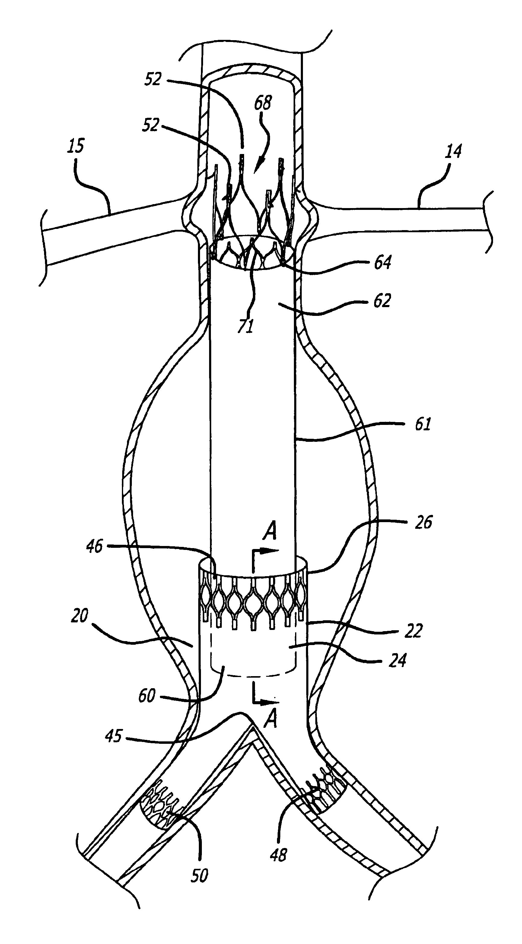
[0027]The present invention is described in the context of providing a device and method for repair of body lumens using a graft assembly. While the description which follows relates to the preferred use of the invention, namely, the repair of the aorta of a patient, the invention may equally be applied to any defective bifurcated vessel of a patient. The terms “superior” and “inferior” as used herein shall mean upstream and downstream respectively. The preferred embodiments of the system and method of the present invention are described below.

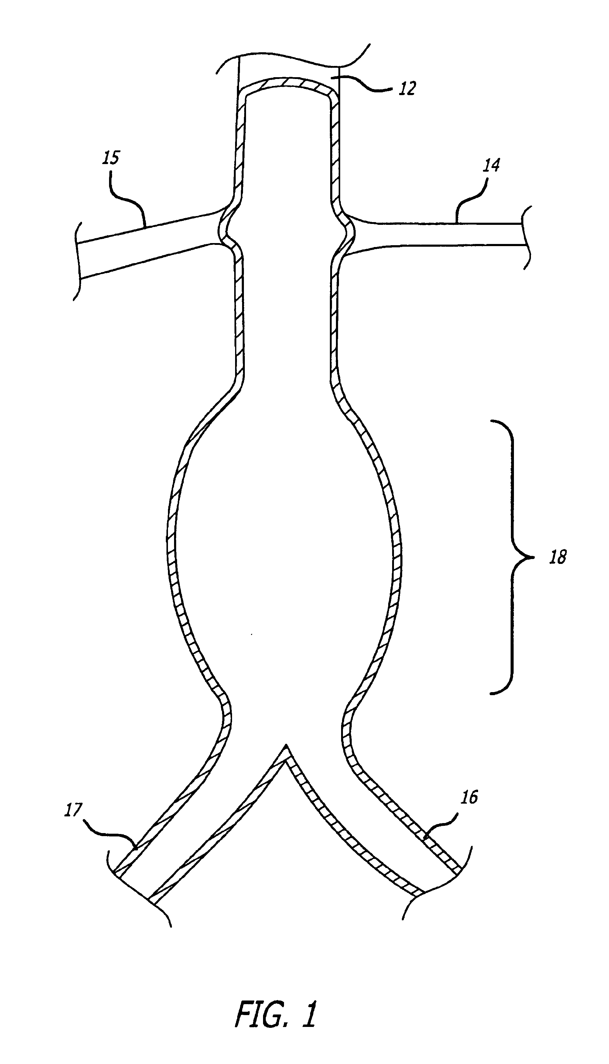
[0028]A site for the potential use of the present invention is exemplified in FIG. 1, which is a schematic depiction of the vascular system of a patient showing the relationship of the aorta 12 to the left and right renal arteries 14, 15 and the left and right iliac arteries 16, 17 and also showing a diseased portion 18 of the aorta below the renal arteries dilated by an aneurysm. (Left and right are described as from the viewpoint of the pati...


PUM


Abstract

The present invention is a bifurcated modular graft for repairing body lumens. In one embodiment, the graft includes two elements, each element being fabricated from material which is flexible. The first element embodies a tubular docking section which bifurcates into left and right tubular limbs. The first element is adapted to be inserted into vasculature of a patient so that the device spans and is supported by a point of bifurcation. The second element is made from a single tubular segment and is adapted to engage the docking section of the first element. The first and second elements are sealed to each other and within the vasculature by expanding support structures.

Description

BACKGROUND OF THE INVENTION[0001]The present invention relates to intraluminal grafts which are used for repairing defects in vessels and other lumens within the body. More particularly, the present invention relates to methods and systems for the endovascular repair of a defect using a flexible bifurcated modular graft.[0002]Aneurysms are discrete dilations of the arterial wall. One of the most common, and among the most life threatening, is an aneurysm of the abdominal aorta between the renal and iliac arteries. If untreated, the aneurysm dilates progressively with an ever increasing risk of rupture and hemorrhagic death.[0003]One method of treatment is provided by direct surgical intervention, in which the defective vessel may be bypassed or replaced using a prosthetic device such as a synthetic graft. The risks involved in direct surgical intervention of this magnitude are great, and include an extensive recovery period.[0004]In recent years, a less invasive method of treatment ...

Claims


Application Information

Patent Timeline
Patent Type & Authority Patents(United States)
IPC IPC(8): A61F2/06
CPCA61F2/07A61F2002/067A61F2/848A61F2/89A61F2002/075A61F2230/0013A61F2220/0016
Inventor CHUTER, TIMOTHY A. M.
Owner TIMOTHY A M CHUTER M D
Features
  • Generate Ideas
  • Intellectual Property
  • Life Sciences
  • Materials
  • Tech Scout
  • Unparalleled Data Quality
  • Higher Quality Content
  • 60% Fewer Hallucinations
Learn More