
Method for controlling an adjuster on a motor vehicle

a technology for motor vehicles and adjusters, applied in the direction of motor/generator/converter stoppers, dynamo-electric converter control, instruments, etc., can solve the problems of significant position errors, significant reduction of adjusting path, measurement errors, etc., to reduce adjusting energy and associate the positions of memory positions with adjusting positions more easily.

Inactive Publication Date: 2005-09-13
BROSE FAHRZEUGTEILE GMBH & CO KG
View PDF9 Cites 15 Cited by
  • Summary
  • Abstract
  • Description
  • Claims
  • Application Information

AI Technical Summary

Benefits of technology

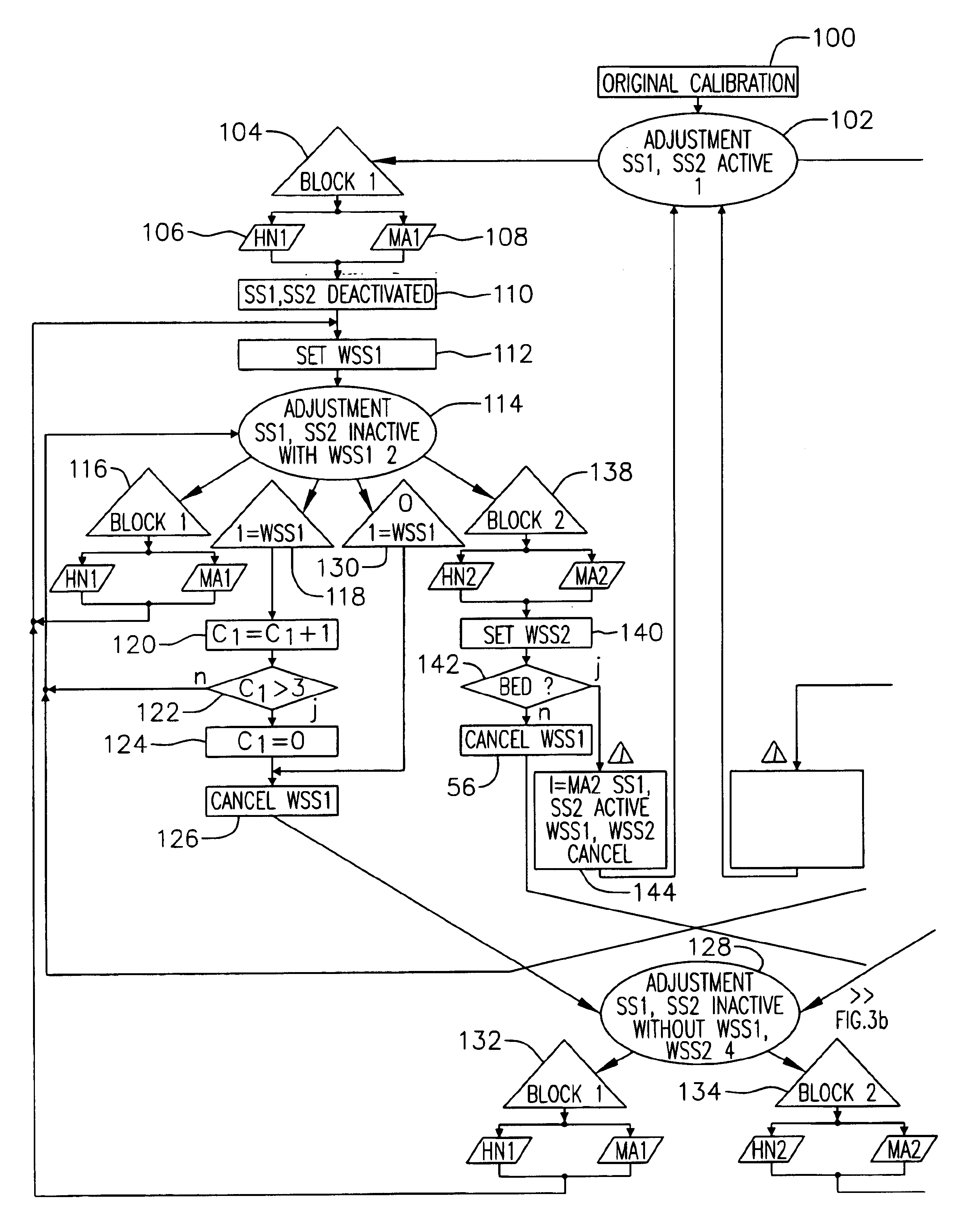
The present invention relates to a method for controlling an adjusting device on a motor vehicle, such as a seat adjuster. The method includes setting an adjustment position of the adjusting device responsive to a user action, determining a set adjustment position in response to a certain condition dependent on the adjusting motion, and inactivating a protective stop to reduce the energy of the adjusting motion. The protective stop cannot be inactivated by the user and is set based on the position of the mechanical stop. The method also includes using an evaluating logic to monitor and evaluate the adjusting motion and learning a new protective stop based on the position of the mechanical stop. The learning region controls local peripheral conditions for learning a new protective stop. The invention allows for the setting of a new protective stop when needed and ensures that the energy of the adjusting motion is reduced without limiting the adjusting path.

Problems solved by technology

This type of indirect measuring of the adjustment position by detecting the drive movement however leads to measuring errors as a result of inaccuracies between the detected position and the actual adjustment position which can differ here significantly from each other.
If an adjuster on a vehicle seat is actuated repeatedly, for example through frequent change of driver then this can lead to significant position errors.
The significant position errors previously explained moreover cause a displacement of the positions of the protective stops from or to the actual mechanical stops whose positions remain fixed relative to the displacement.
An unfavourable displacement of the protective stops with increasing distance from the mechanical stops would lead to a significant reduction in the adjusting path if the protective stops are to prevent overrun, for example through inertia, in the direction of the mechanical stops for reasons of loads.
The problem here is that through user actions of this kind a repeated hard run into the mechanical stops which limit the adjusting path can take place, with a corresponding strain on the adjuster.

Method used


Image

  • Method for controlling an adjuster on a motor vehicle
  • Method for controlling an adjuster on a motor vehicle
  • Method for controlling an adjuster on a motor vehicle

Examples


Embodiment Construction

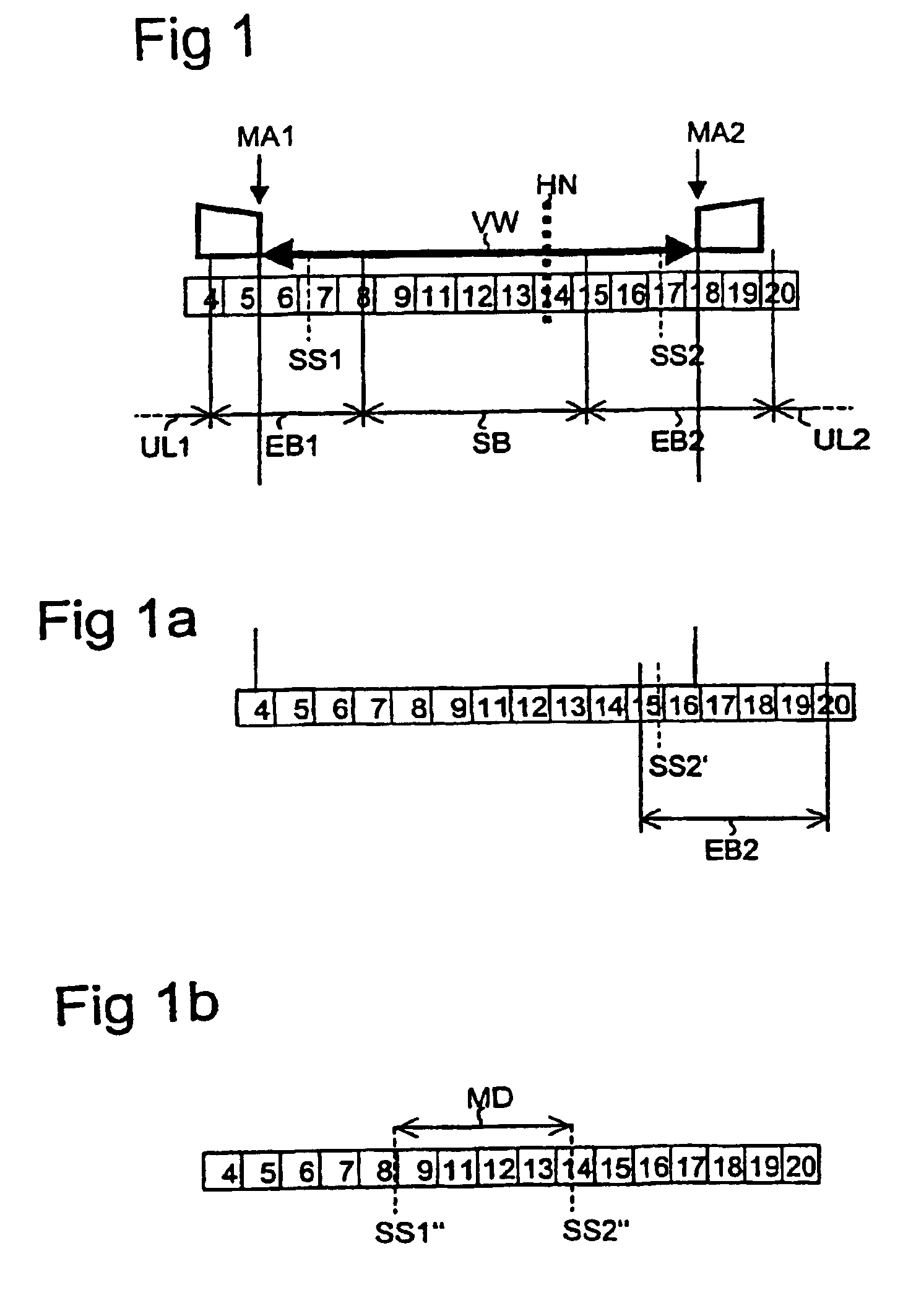
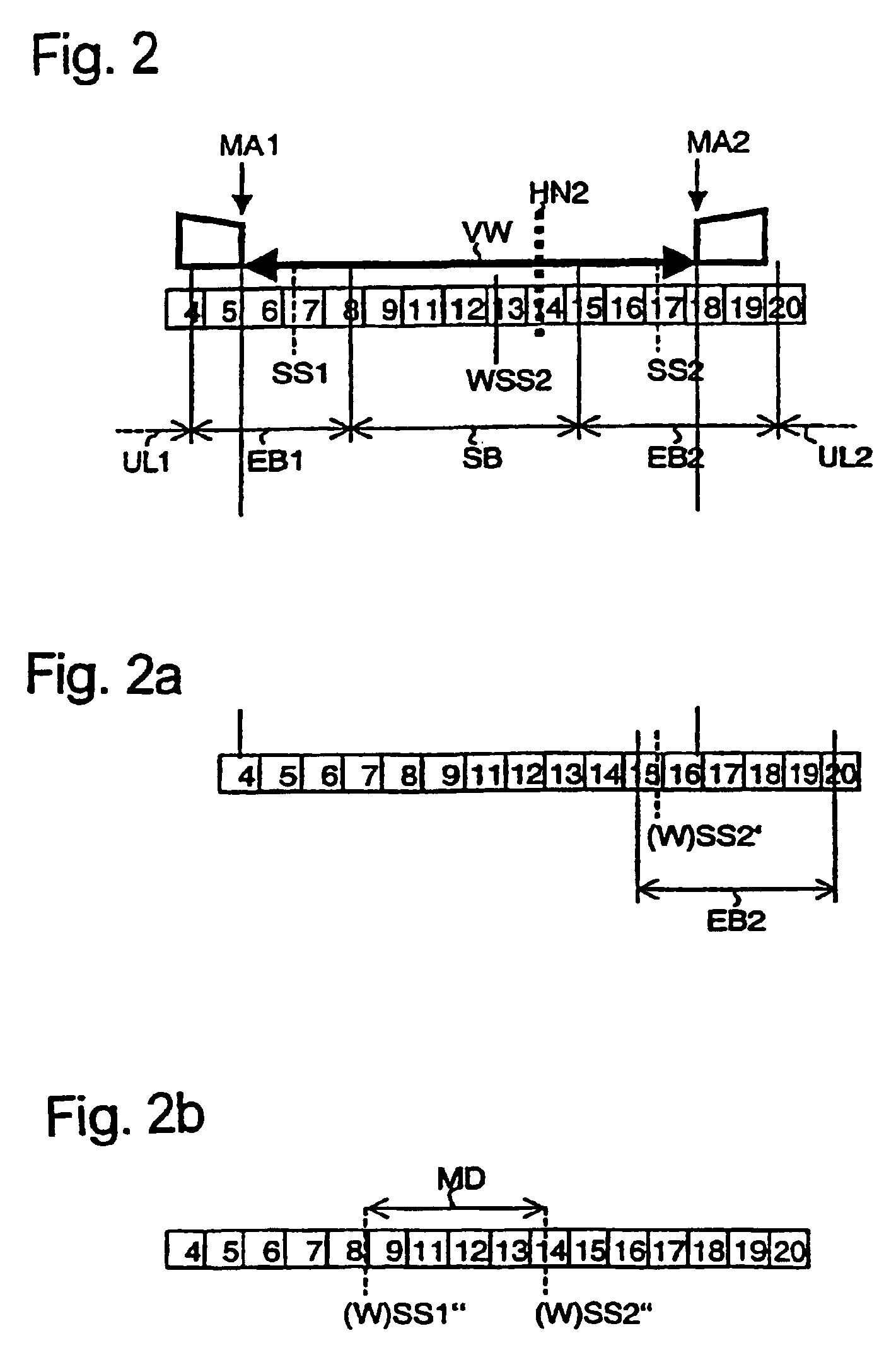
[0098]FIG. 1 illustrates an adjusting path VW of a vehicle seat adjuster according to one embodiment of the invention. The adjusting path VW extends from a first mechanical stop MA1 (left) up to a second mechanical stop MA2 (right). By way of example in the present embodiment this is a seat longitudinal adjuster, a head restraint adjuster, or another translational adjuster conventional in the art. A person of skill in the art will recognize that the method for controlling the longitudinal adjuster may also be applied to rotational adjusters, such as adjusting the incline of the seat backrest.

[0099]The actual position of the adjustable part of the adusting device is determined by an evaluation device which in the present embodiment evaluates the adjusting motion via an incremental transmitter and an associated sensor. The adjusting path VW is, in one example divided into a number of increments. In the illustration of FIG. 1 the adjusting path VW extends from the increment with the nu...


PUM


Abstract

A method for controlling a vehicle seat adjuster in an adjusting path having a first mechanical stop and a second mechanical stop. A user sets an adjustment position of the adjuster inside the adjusting path. A protective stop is also automatically set in the adjusting path in the vicinity of the mechanical stops or another mechanical block blocking the adjusting path. The protective stop causes the adjusting motion to be reduced or stopped upon reaching of the protective stop. This helps produce a smooth braking of the vehicle seat and reduces the mechanical strain on the mechanical stops. The protective stop may be corrected with an updated protective stop. The updated protective stop is maintained despite any user action if a condition dependent on the adjusting motion of the adjuster is fulfilled. Learning regions within the adjusting path are provided to allow the setting of updated protective stops within the learning regions.

Description

CROSS-REFERENCE TO RELATED APPLICATION(S)[0001]This application is a National Phase Patent Application of International Application Number PCT / DE02 / 04469, filed on Dec. 2, 2002, which claims priority of German Patent Application Number 101 59 136.5, filed on Dec. 1, 2001, German Patent Application Number 102 19 284.7, filed on Apr. 30, 2002, German Patent Application Number 102 24 626.2, filed on Jun. 4, 2002, and German Patent Application Number 102 26 006.0, filed on Jun. 12, 2002.FIELD OF THE INVENTION[0002]The invention relates to a method for controlling an adjuster on a motor vehicle, more particularly a vehicle seat adjuster.BACKGROUND[0003]A method of this kind relates in particular to the control of an adjuster which has at least one adjusting path between a first stop and a second stop and in which an adjustment position of the adjuster can be set within the adjusting path by a user action. The relevant adjustment position within the adjusting path is hereby determined (by...

Claims


Application Information

Patent Timeline
Patent Type & Authority Patents(United States)
IPC IPC(8): B60N2/02B60N2/06B60N2/90
CPCB60N2/0224B60N2/0244B60N2/06B60N2002/0272B60N2/0272B60N2210/14B60N2/0277B60N2220/20B60N2/0226
Inventor WOLLER, ALEXANDERCARL, INGOSTEINER, MICHAELFUCHS, THORSTENSCHIEGEL, STEFANROSCH, THOMAS
Owner BROSE FAHRZEUGTEILE GMBH & CO KG
Learn More