

Optical amplifier with damped relaxation oscillation
- Summary
- Abstract
- Description
- Claims
- Application Information
AI Technical Summary
Benefits of technology
Problems solved by technology
Method used
Image

Examples
Embodiment Construction
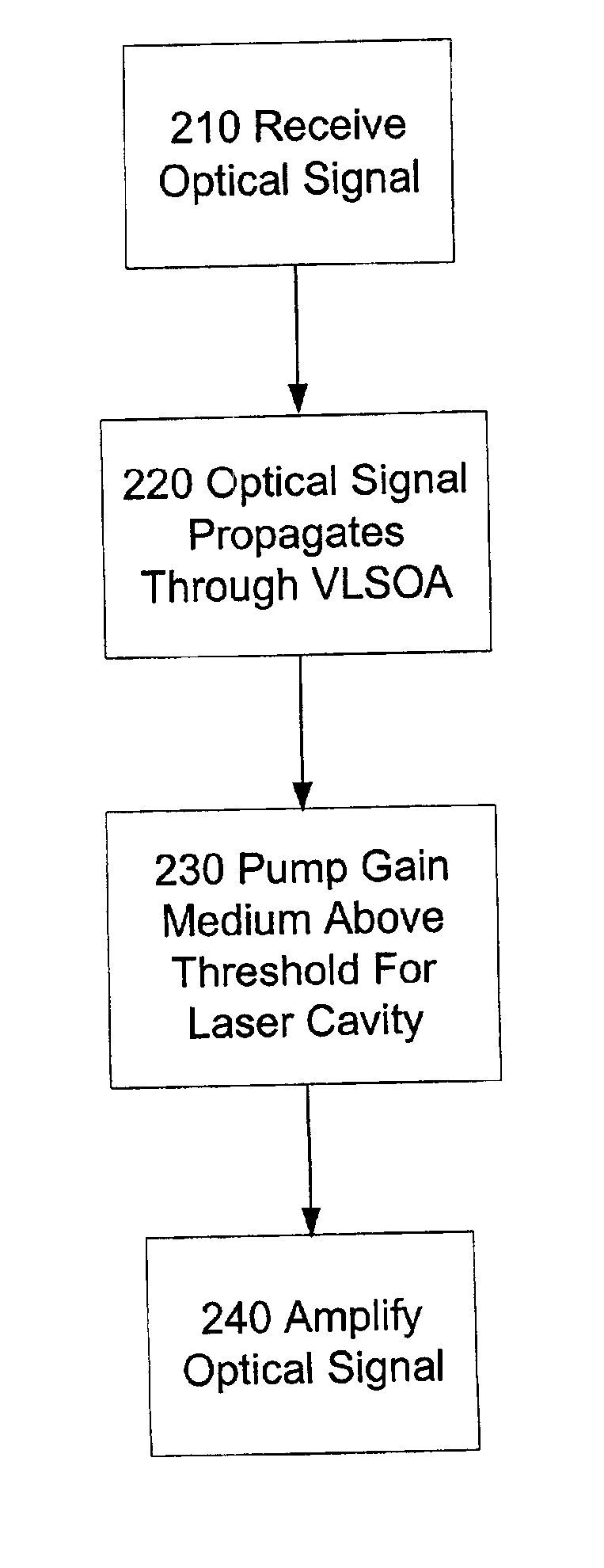
[0023]The invention is directed to damping relaxation oscillations in optical amplifiers. Fluctuations in the gain of an optical amplifier can occur at the relaxation oscillation frequency of an optical amplifier. By damping the relaxation oscillations, gain fluctuations are reduced. Thus, damping the relaxation oscillations improves the gain performance of an optical amplifier.
[0024]Introduction: Basic Theory:
[0025]What follows is a brief description of one mathematical model of relaxation oscillation, damping, and gain perturbation.
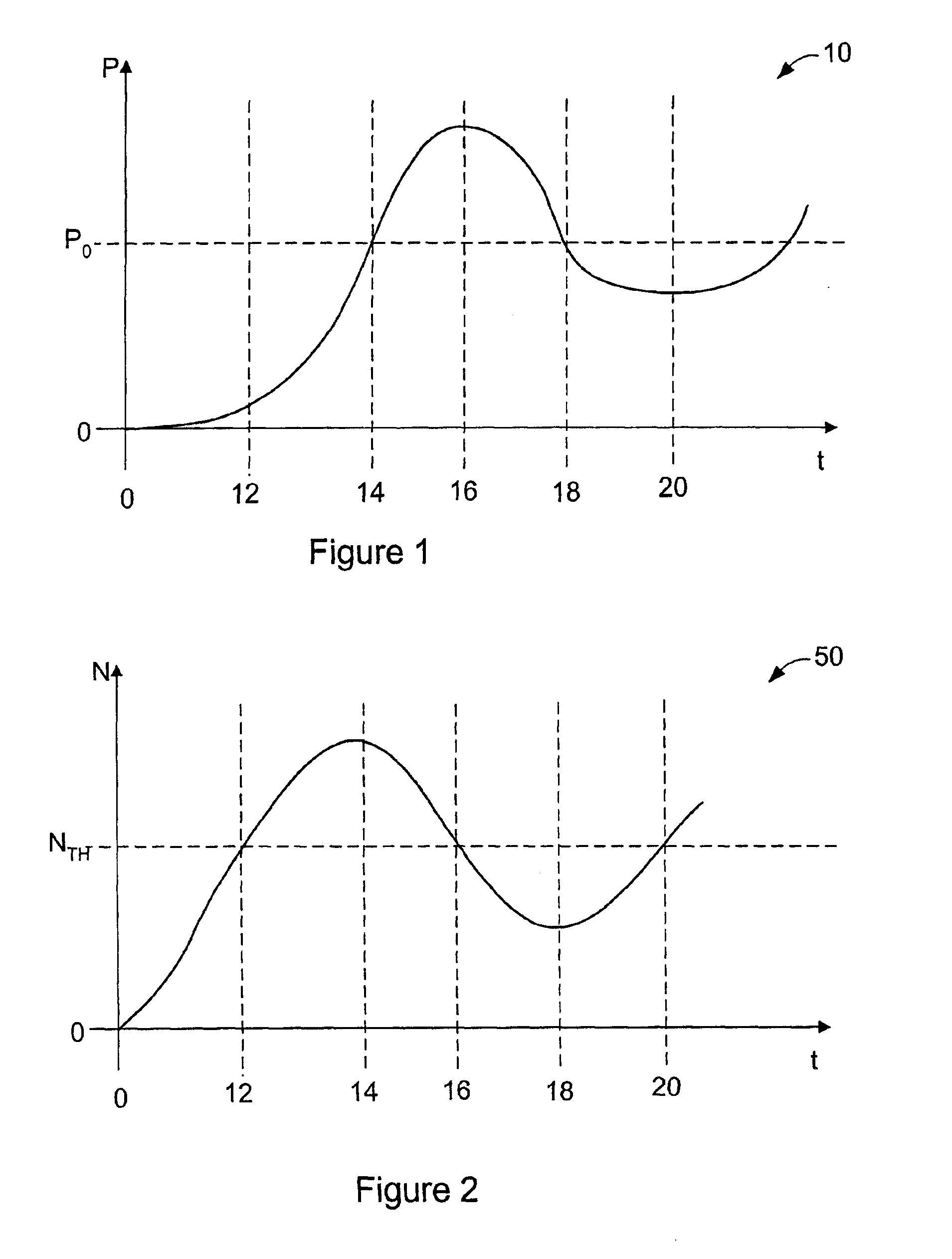
[0026]Relaxation oscillation can be understood with respect to a semiconductor laser using the following equations and the graphs in FIGS. 1 and 2.
[0027]The following equation describes the change in carrier density, N, as time changes: ⅆNⅆt=Jed-A(N-N0)P-NτN(1)
[0028]The following equation describes the change in photon density of the lasing field, P, as time changes: ⅆPⅆt=Γ A(N-N0)P-PτP+βNτN(2)
[0029]In equations (1) and (2), J is the pumping curr...
PUM
 Abstract
Description
Claims
Application Information