Planar laser

a laser and planar technology, applied in the field of optical devices, can solve the problems of plastic not having the desired thermal stability for many applications, the effect of cladding pumping in the practice of pure three-level laser pumping, and the limited application of double-clad amplifiers and lasers to 4-level systems

Inactive Publication Date: 2005-09-13
CORNING INC
View PDF16 Cites 41 Cited by
  • Summary
  • Abstract
  • Description
  • Claims
  • Application Information

AI Technical Summary

Problems solved by technology

However, the cladding-pumped technique has been determined in practice to be ineffective for pumping pure three-level lasers, such as the 980 nm transition of ytterbium, because of various laser design parameters that have to be satisfied.
Practical double-clad amplifiers and lasers have been mostly limited to 4-level systems.
Such plastic may not have the desired thermal stability for many applications, may delaminate from the first cladding, and may be susceptible to moisture damage.
One of the primary technical challenges in a high power fiber laser is the formation of the input dielectric mirror across the multimode inner cladding of the double-clad fiber.
Approaches include attaching a glass micro-sheet to the fiber endface or directly depositing a thin-film dielectric on the fiber endface, but both of these methods present their own technical hurdles.
However, an increased index delta for providing power enhancement requires more design, testing, and manufacturing complexities to be first solved.

Method used


Image

  • Planar laser
  • Planar laser
  • Planar laser

Examples


Embodiment Construction

[0026]It is to be understood that the following detailed description presents embodiments of the invention, and is intended to provide an overview or framework for understanding the nature and character of the invention as it is claimed. The accompanying drawings are included to provide a further understanding of the invention, and are incorporated into and constitute a part of this specification. The drawings illustrate various embodiments of the invention, and together with the description serve to explain the principles and operations of the invention.

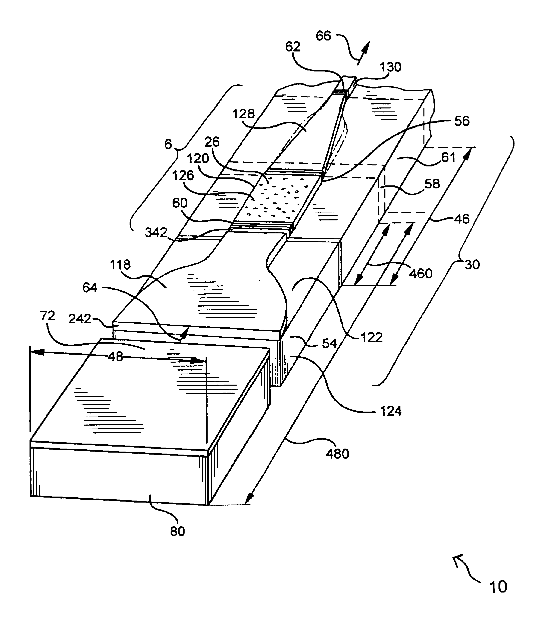
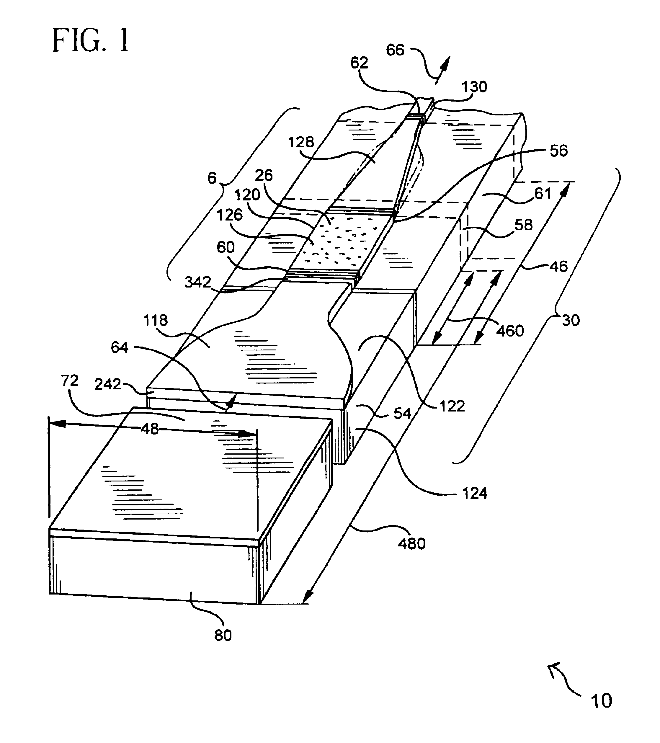
[0027]The optically-active brightness converter 6 forming a portion of a dielectric waveguide laser 30 for providing an optical device 10 of the present invention is shown in FIG. 1 and is generally described and depicted herein with reference to an exemplary or representative embodiment with the same numbers referenced to the same or functionally similar parts. In general, different design considerations need to be traded-off to pr...


PUM


Abstract

An optical device (10) includes a broad area laser (72) for lasing at a first wavelength (64), a multimode active-doped tapered waveguide laser (6); and a multimode passive planar mode transformer (118) coupling and tapering from the broad area laser (72) to the multimode active-doped tapered waveguide laser (6).

Description

CLAIM OF PRIORITY[0001]This is a continuation-in-part of U.S. patent application Ser. No. 09 / 968,354 filed on Sep. 27, 2001, now U.S. Pat. No. 6,751,241, and of U.S. patent application Ser. No. 09 / 808,270, filed on Mar. 14, 2001, now U.S. Pat. No. 6,836,607 the content of which are relied upon and incorporated herein by reference in its entirety, and the benefit of priority under 35 U.S.C. § 120 is hereby claimed.BACKGROUND OF THE INVENTION[0002]1. Field of the Invention[0003]The present invention relates generally to optical devices, and in particular to brightness converters for optical devices.[0004]2. Technical Background[0005]The development of a single transverse mode laser when excited by a gain region that supports the lasing of multiple modes is useful for many different types of applications. The efficient coupling of the output of this laser radiation into single-mode waveguides for subsequent frequency conversion or similar frequency operation is still an area of develop...

Claims


Application Information

Patent Timeline
Patent Type & Authority Patents(United States)
IPC IPC(8): H01S3/06H01S3/067H01S3/063H01S3/094H01S5/20H01S5/00H01S3/0941H01S5/026H01S5/02
CPCH01S3/063H01S3/06716H01S3/0675H01S3/0635H01S3/0672H01S3/06729H01S3/094003H01S3/094019H01S3/094057H01S3/094069H01S3/09415H01S5/0208H01S5/0213H01S5/026H01S5/0655H01S5/2036G02B6/1228
Inventor PRASSAS, MICHELZENTENO, LUIS A.
Owner CORNING INC
Why Eureka
Try Eureka