Ethernet adapting apparatus

Inactive Publication Date: 2005-09-13
LANTIQ BET GMBH & CO KG
View PDF8 Cites 6 Cited by
  • Summary
  • Abstract
  • Description
  • Claims
  • Application Information

AI Technical Summary

Benefits of technology

[0011]Accordingly, it is the object of the present invention to provide an Ethernet adapting apparatus for data transfer which makes it possible to extend an Ethernet local area network to remote locations without reducing the data transfer speed.

Problems solved by technology

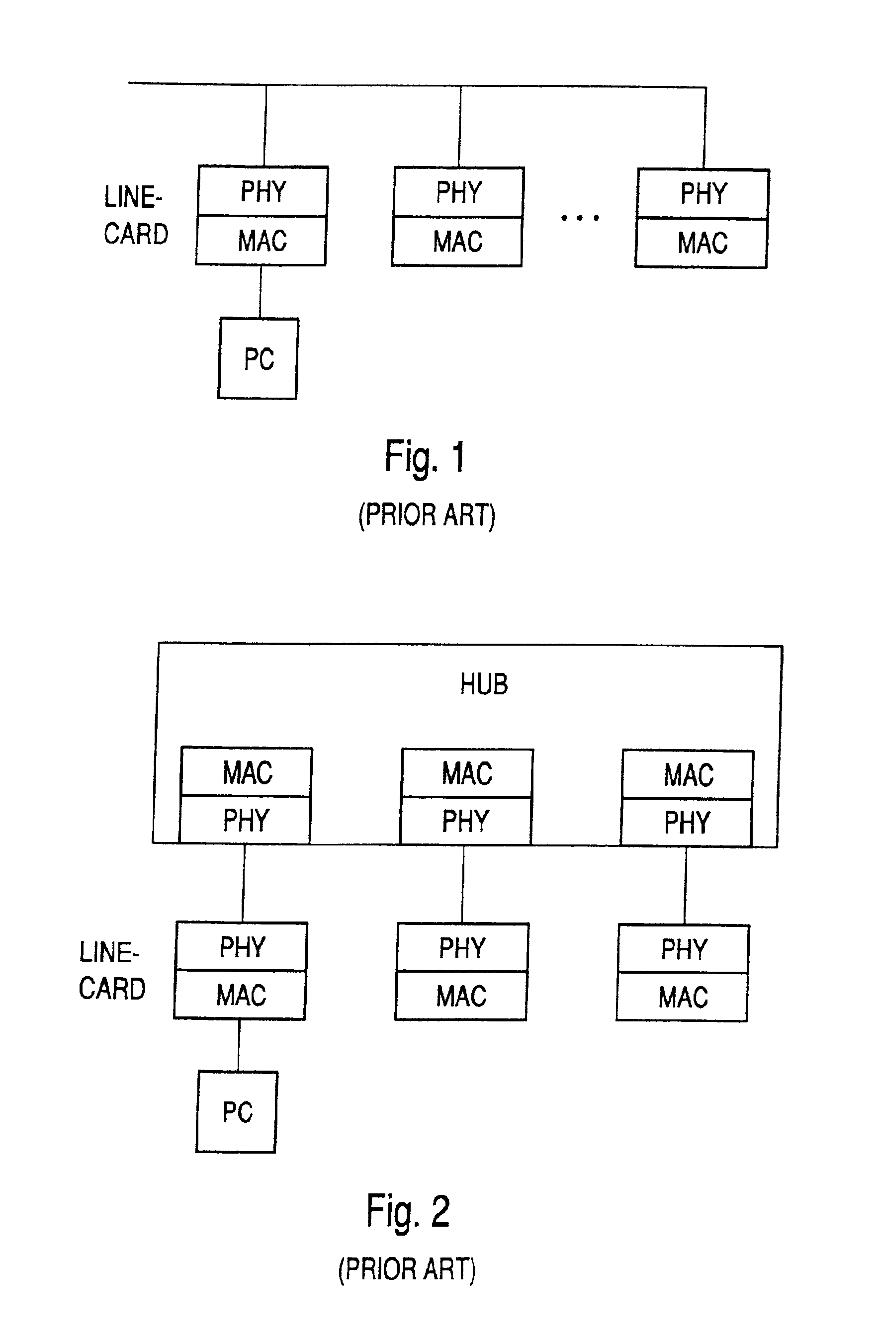
Further, no auto-negotiation procedures between the different line-cards can be performed.
A disadvantage of the system shown in FIG. 5 resides in that there is only one data transmission channel between the two local area networks LANA, LANB.
Consequently, the data transfer speed for data transfer from one local area network to the other local area network is very slow.
A further disadvantage is that two bridge devices are necessary to connect both local area networks.

Method used


Image

  • Ethernet adapting apparatus
  • Ethernet adapting apparatus
  • Ethernet adapting apparatus

Examples


Embodiment Construction

[0048]As can be seen from FIG. 6, an Ethernet local area network 1 including, for example, a switch and several PCs within a building A is connected via lines 2-1, 2—2, 2-3 to the Ethernet adapting apparatuses 3-1a, 3-2a, 3-3a within the same building. Each Ethernet adapting apparatus is connected via a corresponding telephone line 4-1, 4-2, 4-3 to a remote Ethernet adapting apparatus 3-1b, 3-2b, 3-3b in a different building B. In the example shown in FIG. 6, each remote Ethernet adapting apparatus 3-1b, 3-2b, 3-3b of a computer 5-1, 5-2, 5-3 is connected by means of a line 6-1, 6-2, 6-3.

[0049]The Ethernet adapting apparatuses 3-1a, 3-2a, 3-3a within building A are set in a physical PHY mode to emulate the standard Ethernet data pump, whereas the remote Ethernet adapting apparatuses 3-1b, 3-2b, 3-3b within building B are set to a MAC mode for emulating an Ethernet medium access controller. Two Ethernet adapting apparatuses according to the present invention connected via a telecommu...


PUM


Abstract

An Ethernet adapting apparatus for data transfer between a standard Ethernet data pump and an Ethernet medium access controller via telecommunication medium (4), comprising:(a) a dual mode media independent interface (9) which emulates in a PHY mode the standard Ethernet data pump and which emulates in a MAC mode the Ethernet medium access controller;(b) a data pump (10) connected to the telecommunication medium (4);(c) a data buffer (11) for storing at least one Ethernet data package to be transferred between the standard Ethernet data pump and the Ethernet medium access controller.

Description

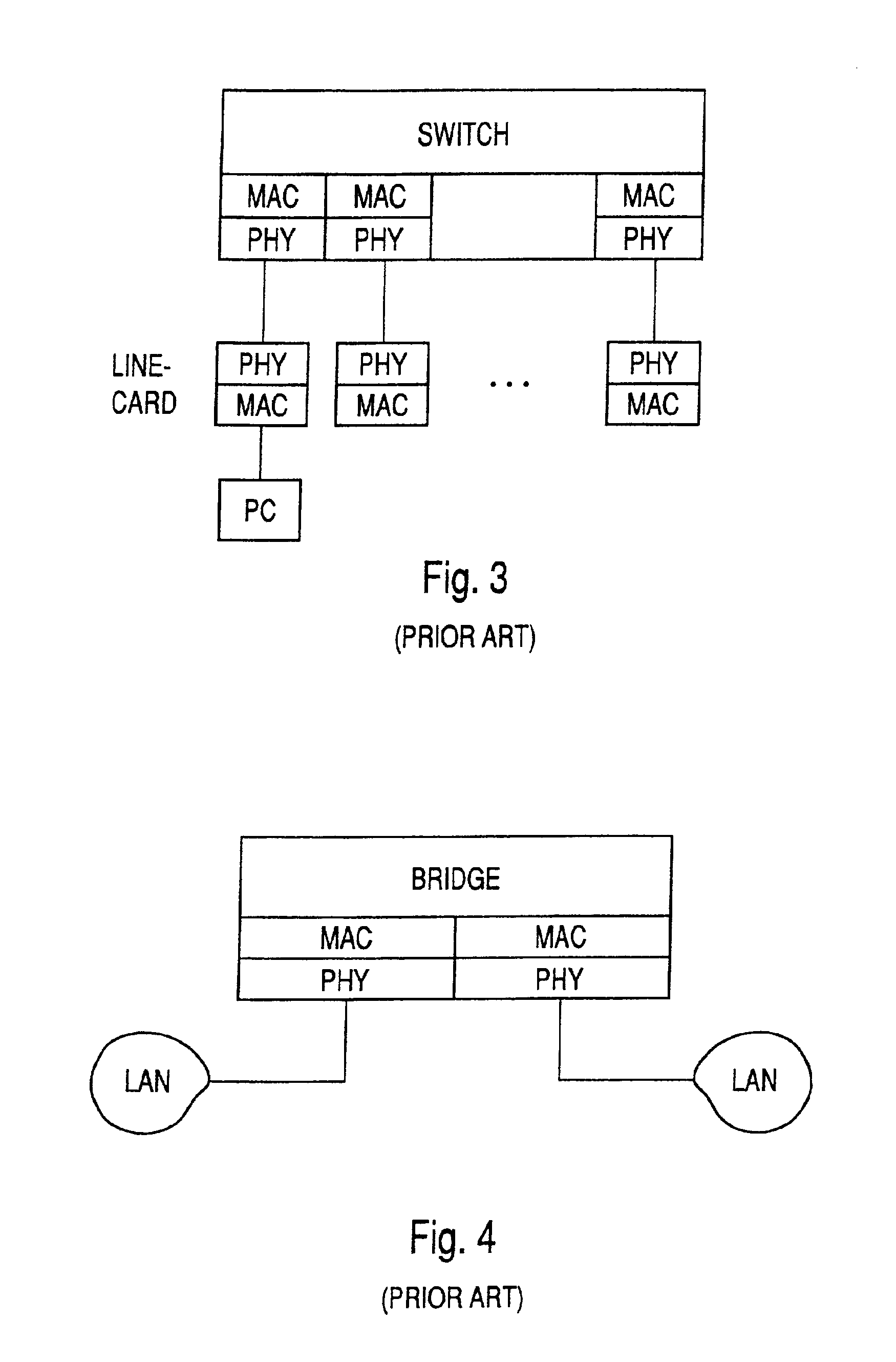
TECHNICAL FIELD[0001]The present invention refers to an Ethernet adapting apparatus for data transfer between a standard Ethernet data pump and an Ethernet medium access controller (MAC) via a telecommunication medium, and in particular via a telephone line.RELATED ART[0002]Ethernet began as a shared media network architecture. Line-cards of a PC are connected to an Ethernet data transfer cable as shown in FIG. 1. In the architecture shown in FIG. 1, only half duplex data transfer is possible. Further, no auto-negotiation procedures between the different line-cards can be performed.[0003]FIG. 2 shows a further Ethernet architecture with a HUB device. A HUB is a component that serves as a common termination point for multiple nodes and can relay signals along appropriate signal paths. A HUB connects nodes that have a common architecture, such as Ethernet. In the architecture shown in FIG. 2, all data coming from one line-card are sent to all other line-cards comprising a physical lay...

Claims


Application Information

Patent Timeline
IPC IPC(8): H04L12/56H04L12/46H04L49/901
CPCH04L12/4625H04L49/90H04L49/901H04L49/9063H04L49/9078H04L12/40
Inventor ARONSON, SIMCHALAZMI, SHAIHARPAK, AMNON
Owner LANTIQ BET GMBH & CO KG
Why Eureka
Try Eureka