Eureka AIR delivers breakthrough ideas for toughest innovation challenges, trusted by R&D personnel around the world.

Miter saw with improved safety system

a safety system and miter saw technology, applied in the field of miter saws, can solve the problems of increasing the chance of injury, presenting a risk of injury to users, and limiting the risk of injury to users, and achieve the effect of limiting or even preventing injury to users

Inactive Publication Date: 2005-09-20
SAWSTOP HLDG LLC
View PDF249 Cites 142 Cited by
  • Summary
  • Abstract
  • Description
  • Claims
  • Application Information

AI Technical Summary

Benefits of technology

[0004]Miter saws are a type of woodworking machinery used to cut workpieces of wood, plastic and other materials. Miter saws typically include a base upon which workpieces are placed and include a circular saw blade mounted on a pivot arm. A person uses a miter saw by placing a workpiece on the base beneath the upraised blade and then bringing the blade down via the pivot arm to cut the workpiece. Miter saws present a risk of injury to users because the spinning blade is often exposed when in use. Furthermore, users often use their hands to position and support workpieces beneath the blade, which increases the chance that an injury will occur.
[0005]The present invention provides a miter saw with an improved safety system that is adapted to detect the occurrence of one or more dangerous, or triggering, conditions during use of the miter saw, such as when a user's body contacts the spinning saw blade. When such a condition occurs, the safety system is actuated to limit or even prevent injury to the user.

Problems solved by technology

Miter saws present a risk of injury to users because the spinning blade is often exposed when in use.
Furthermore, users often use their hands to position and support workpieces beneath the blade, which increases the chance that an injury will occur.

Method used


Image

  • Miter saw with improved safety system
  • Miter saw with improved safety system
  • Miter saw with improved safety system

Examples


Embodiment Construction

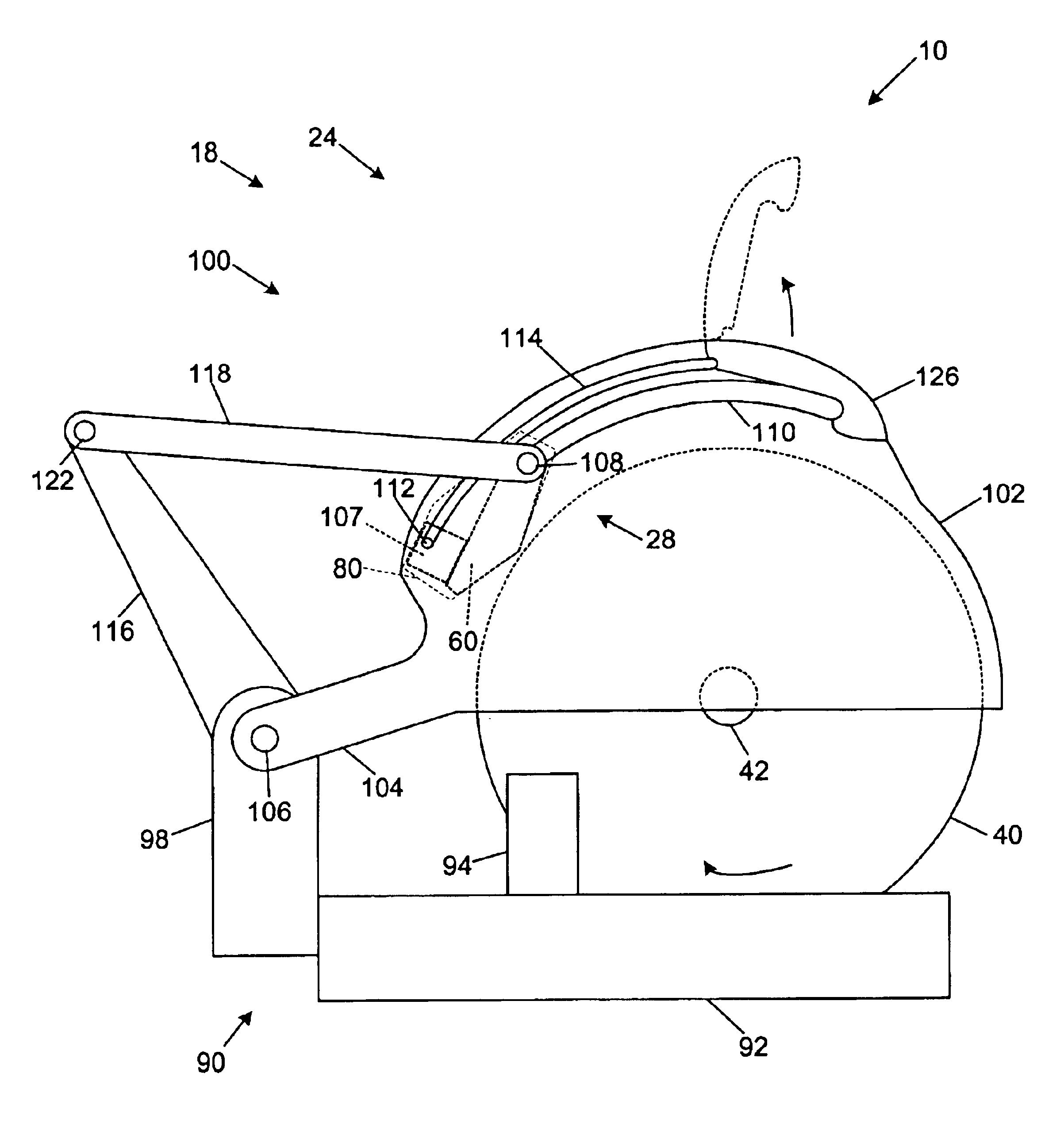
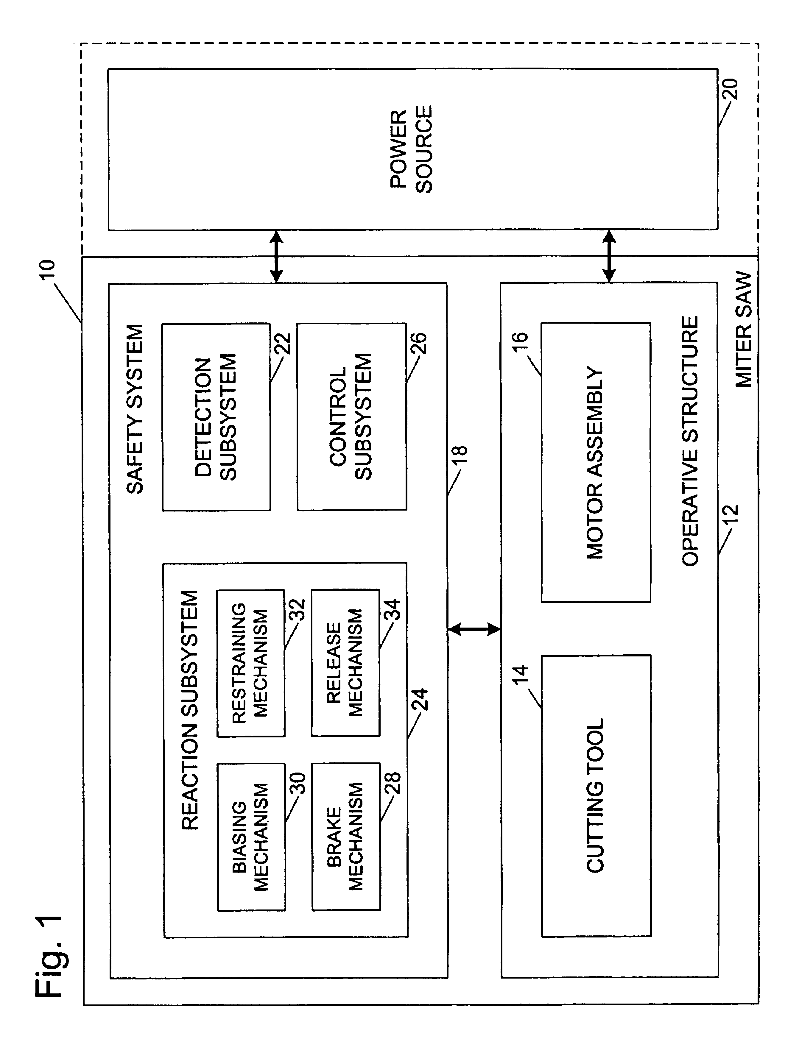
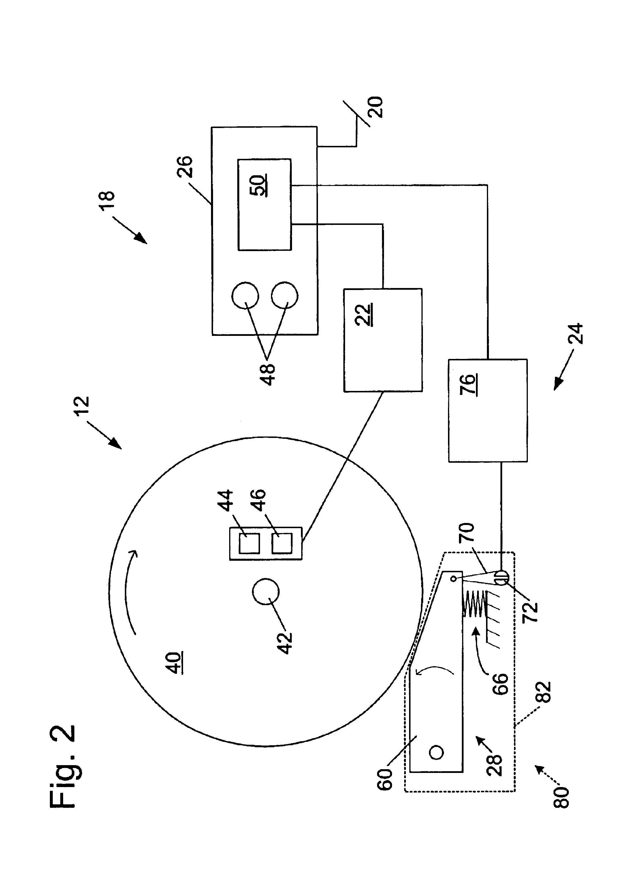
[0019]A miter saw according to the present invention is shown schematically in FIG. 1 and indicated generally at 10. Miter saw 10 may be any of a variety of different types and configurations of miter saw adapted for cutting workpieces, such as wood, plastic, etc. Miter saw 10 includes an operative structure 12 having a cutting tool 14 and a motor assembly 16 adapted to drive the cutting tool. Miter saw 10 also includes a safety system 18 configured to minimize the potential of a serious injury to a person using miter saw 10. Safety system 18 is adapted to detect the occurrence of one or more dangerous, or triggering, conditions during use of miter saw 10. If such a dangerous condition is detected, safety system 18 is adapted to engage operative structure 12 to limit any injury to the user caused by the dangerous condition.

[0020]Miter saw 10 also includes a suitable power source 20 to provide power to operative structure 12 and safety system 18. Power source 20 may be an external po...


PUM

PropertyMeasurementUnit
angular momentumaaaaaaaaaa
rotationaaaaaaaaaa
perimeteraaaaaaaaaa

Abstract

A miter saw is disclosed having a base, a blade supported by the base, a detection system adapted to detect a dangerous condition between a person and the blade, and a reaction system associated with the detection system to cause a predetermined action to take place upon detection of the dangerous condition. The blade is rotatable, and moves into a cutting zone to cut a workpiece. The predetermined action may be to stop the blade from rotating, to create an impulse against movement of the blade into the cutting zone, or to cause the blade to move away from the cutting zone.

Description

CROSS-REFERENCE TO RELATED APPLICATIONS[0001]This application is a continuation-in-part of the following U.S. patent applications: Ser. No. 09 / 676,190, filed Sep. 29, 2000, Ser. No. 09 / 929,221, filed Aug. 13, 2001, Ser. No. 09 / 929,226, filed Aug. 13, 2001, Ser. No. 09 / 929,227, filed Aug. 13, 2001, Ser. No. 09 / 929,234, filed Aug. 13, 2001, Ser. No. 09 / 929,235, filed Aug. 13, 2001, Ser. No. 09 / 929,236, filed Aug. 13, 2001, Ser. No. 09 / 929,237, filed Aug. 13, 2001, Ser. No. 09 / 929,238, filed Aug. 13, 2001, Ser. No. 09 / 929,240, filed Aug. 13, 2001, Ser. No. 09 / 929,241, filed Aug. 13, 2001, Ser. No. 09 / 929,242, filed Aug. 13, 2001, Ser. No. 09 / 929,244, filed Aug. 13, 2001, Ser. No. 09 / 929,425, filed Aug. 13, 2001, and Ser. No. 09 / 929,426, filed Aug. 13, 2001, all currently pending.[0002]This application claims the benefit of and priority from the following U.S. Provisional Patent Applications: Ser. No. 60 / 270,011, filed Feb. 20, 2001, Ser. No. 60 / 270,941, filed Feb. 22, 2001, Ser. No. 60...

Claims


Application Information

Patent Timeline
Patent Type & Authority Patents(United States)
IPC IPC(8): B23D45/06B23D59/00B23D47/00B23D55/08B23D55/00B23D47/08B23D45/00B27B13/00B27B5/00B27B13/14B27B5/38B27G19/00B27G19/02F16P3/14F16P3/00F16P3/12
CPCB23D45/06B23D47/08B23D55/08B23D59/001B27B5/38F16P3/148B27G19/00B27G19/02F16P3/12F16P3/14B27B13/14Y10S83/01Y10T83/081Y10T83/7726Y10T83/7788Y10T83/8773Y10T83/8786Y10T83/7697Y10T83/089
Inventor GASS, STEPHEN F.FULMER, J. DAVIDHUEBNER, RANDALL J.
Owner SAWSTOP HLDG LLC
Why Eureka
Eureka Blog
Learn More