Water heater

a water heater and water tank technology, applied in the field of water heaters, can solve the problems of requiring a relatively large installation space, water heaters are bulky in volume, and water heaters are not efficient enough to meet the needs of domestic hot water supply,

Inactive Publication Date: 2005-09-20
GRAND HALL ENTERPRISE COMPANY
View PDF4 Cites 36 Cited by
  • Summary
  • Abstract
  • Description
  • Claims
  • Application Information

AI Technical Summary

Benefits of technology

[0007]It is the primary object of the present invention to provide an improved water heater which has a high efficiency.
[0008]It is another object of the present invention to provide an improved water heater which will draw secondary air into the combustion chamber for providing complete combustion as well as reducing the temperature of the inner surface of the inner cylindrical passage thereby prolonging the service life of the heat exchanger.
[0009]It is another object of the present invention to provide an improved water heater which can supply hot water at a steady temperature.
[0010]It is still another object of the present invention to provide an improved water heater which has a low pressure drop when two or more faucets connected with the water heater are opened for use.
[0011]It is still another object of the present invention to provide an improved water heater which is self-cleaning thereby preventing the accumulation of water scales.
[0013]It is a further object of the present invention to provide an improved water heater in which the water reservoir is positioned surrounding the heat exchanger thereby eliminating the insulation for protection from combustion area.

Problems solved by technology

Nevertheless, such a water heater is bulky in volume, requiring a relatively large space for installation.
Further, the efficiency of such a water heater is only 60% and it takes about 40–60 minutes to heat up the water and the temperature of the water heater cannot be adjusted.

Method used


Image

  • Water heater
  • Water heater
  • Water heater

Examples


Embodiment Construction

[0020]For the purpose of promoting an understanding of the principles of the invention, reference will now be made to the embodiment illustrated in the drawings. Specific language will be used to describe same. It will, nevertheless, be understood that no limitation of the scope of the invention is thereby intended, alterations and further modifications in the illustrated device, and further applications of the principles of the invention as illustrated herein being contemplated as would normally occur to one skilled in the art to which the invention relates.

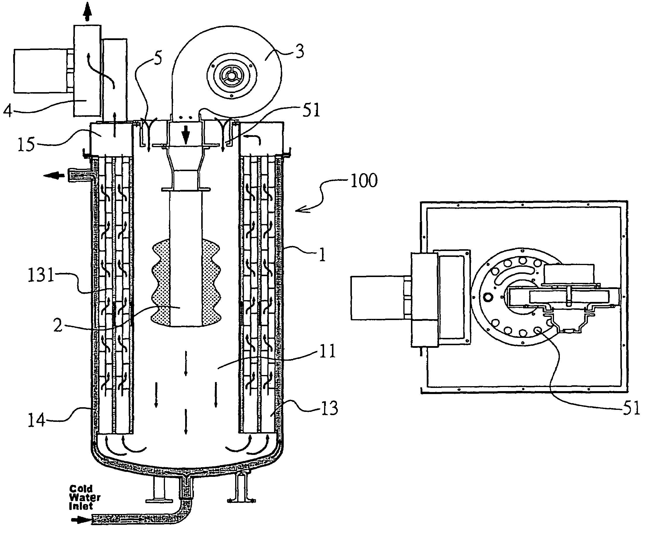
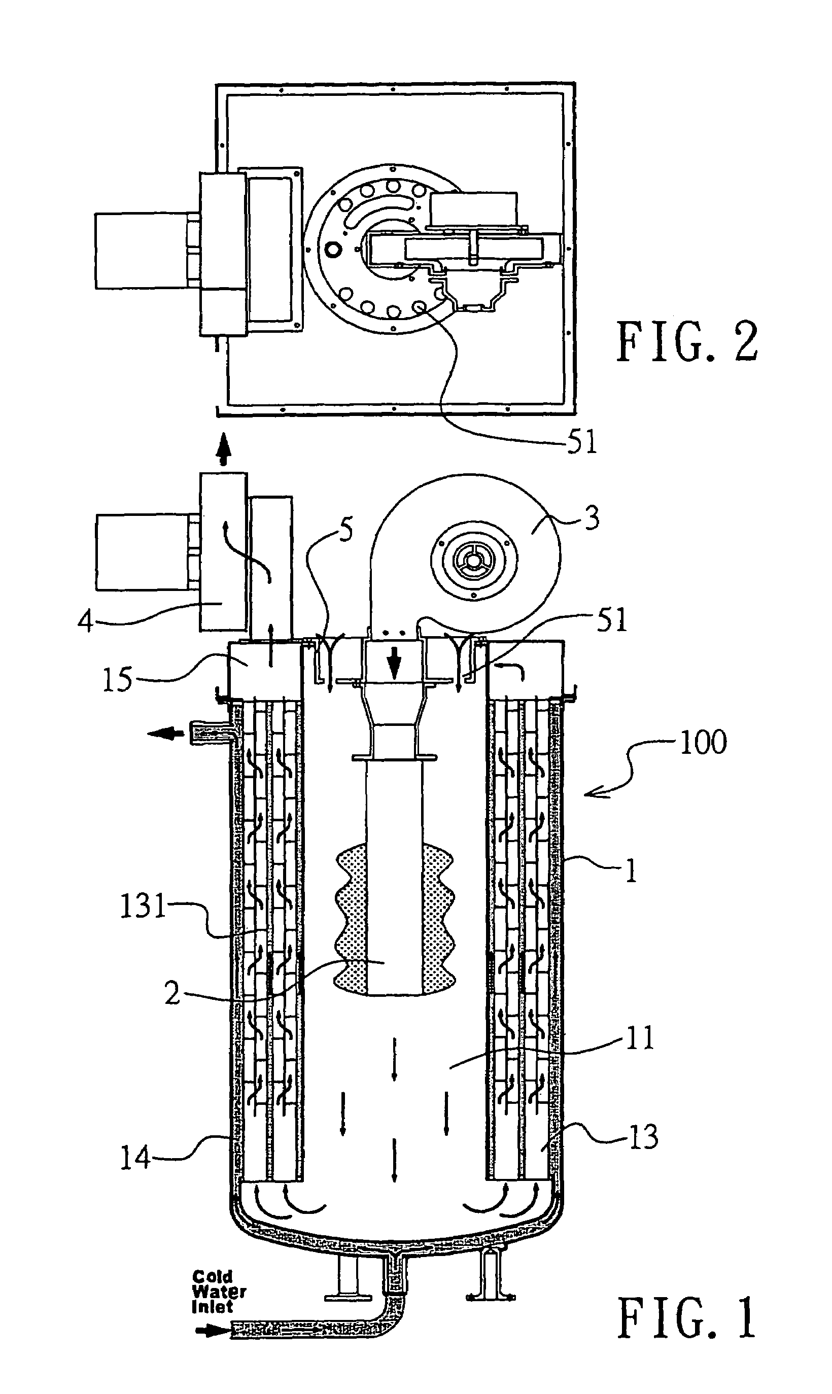
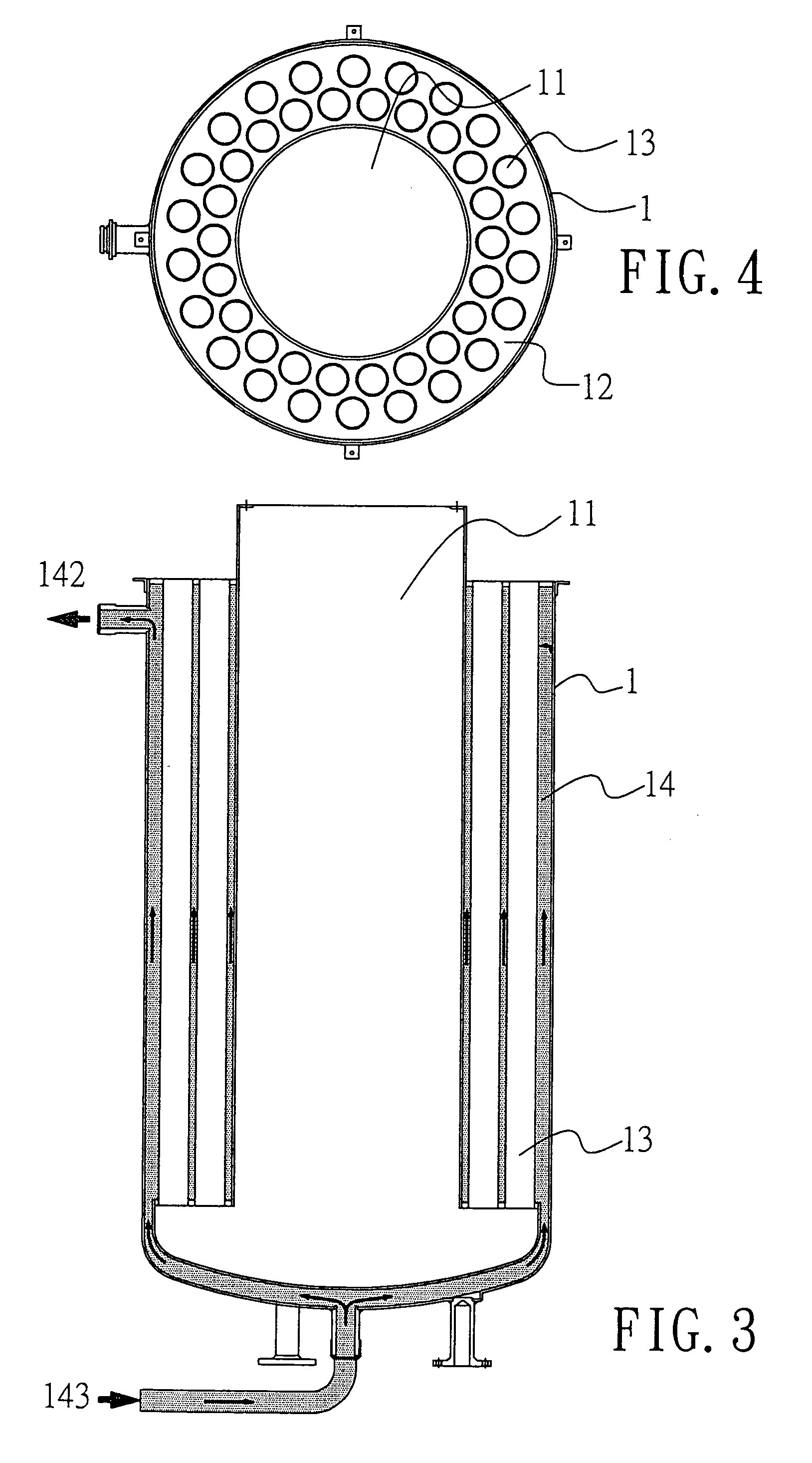
[0021]With reference to FIGS. 1 and 2, the water heater 100 according to the present invention mainly comprises a heat exchanger 1, a gas burner 2, a push blower 3, a pull blower 4, and a top panel 5. As shown in FIGS. 3 and 4, the heat exchanger 1 is a cylindrical housing formed with an inner cylindrical passage 11 at the center and an annular outer passage 12 surrounding the inner cylindrical passage 11. A plurality of flue tu...


PUM


Abstract

A water heater which includes a heat exchanger having a first passage and a second passage connected with the first passage, a gas burner mounted within the first passage, a push blower having an outlet conmected with the gas burner for forcing air into the gas burner, and a water reservoir mounted surrounding the heat exchanger, whereby when the gas burner is turned on, the push blower will be turned on to force air into the gas burner thereby forcing combustion air generated from fire of the gas burner to move along the first passage and meanwhile the pull blower will be turned on to extract the hot air out of the second passage.

Description

BACKGROUND OF THE INVENTION[0001]1. Field of the Invention[0002]This invention is related to a water heater and in particular to one which can supply hot water continuously at a steady temperature and low drop in pressure.[0003]2. Description of the Prior Art[0004]The conventional storage water heater simply comprises a housing with a flue tube at the center, a burner mounted under the flue tube, a cold water inlet pipe extending downwardly through the housing, and a hot water outlet extending upwardly through the housing. Nevertheless, such a water heater is bulky in volume, requiring a relatively large space for installation. Further, the efficiency of such a water heater is only 60% and it takes about 40–60 minutes to heat up the water and the temperature of the water heater cannot be adjusted.[0005]Therefore, it is an object of the present invention to provide an improved water heater which can obviate and mitigate the above-mentioned drawbacks.SUMMARY OF THE INVENTION[0006]This...

Claims


Application Information

Patent Timeline
Patent Type & Authority Patents(United States)
IPC IPC(8): F23C7/00F23C7/02F23L9/00F24H1/22F24H1/26F24H9/00
CPCF23C7/02F23L9/00F24H1/263F24H9/0026F23L5/02
Inventor RYOO, YOUNG
Owner GRAND HALL ENTERPRISE COMPANY
Why Eureka
Try Eureka