Method and device for forming a shed in a weaving machine

a technology of weaving machine and shed, which is applied in the field of weaving shed, can solve the problems of placing a large amount of stress on the warp yarn, and reducing the slashing process time-consuming, so as to improve the quality of the woven fabric, reduce the number of warp breaks, and increase the efficiencies of the weaving machin

Inactive Publication Date: 2005-09-20
GENDELMAN MIKHAIL +1
View PDF17 Cites 5 Cited by
  • Summary
  • Abstract
  • Description
  • Claims
  • Application Information

AI Technical Summary

Benefits of technology

[0009]Another object of the present invention is to improve the quality of the woven fabrics that are woven on a weaving machine using the improved shed-forming device. An additional object of the present invention is to provide a shed-forming device which increases efficiencies of the weaving machines by reducing the number of warp breaks. Another object of the present invention is to reduce friction on the warp yarns and, thereby, in some incidences, allow a reduction in the amount of sizing chemicals needed to treat the yarn for the weaving process and the amount of time the warp yarns spend in the slashing process. A further object is to increase production speeds of the weaving machines.

Problems solved by technology

The shed-forming operation in the current state of the art places a large amount of stress on the warp yarns.
The tension created among the warp beam, the raising and lowering of the harnesses, and the take-up roll causes a relatively large amount of friction on the warp yarns as they travel over the edges of the heddle eyes in both weaving machines utilizing harnesses and jacquard looms.
This slashing process is time-consuming and the chemicals used are expensive.
These warp breaks are time-consuming to fix and can cause off quality fabrics which must be sold at reduced prices.

Method used


Image

  • Method and device for forming a shed in a weaving machine
  • Method and device for forming a shed in a weaving machine
  • Method and device for forming a shed in a weaving machine

Examples


Embodiment Construction

[0036]Reference will now be made in detail to the presently preferred embodiments of the invention, one or more examples of which are shown in the figures. Each example is provided to explain the invention, and not as a limitation of the invention. In fact, features illustrated or described as part of one embodiment can be used with another embodiment to yield still a further embodiment. It is intended that the present invention cover such modifications and variations.

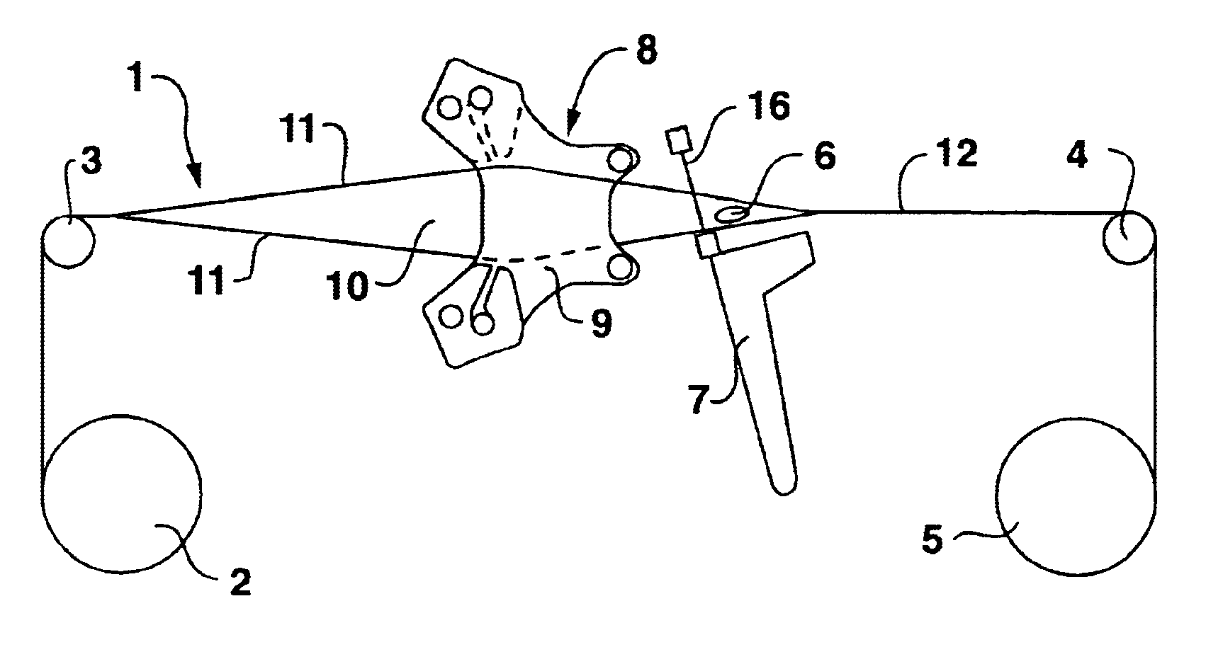
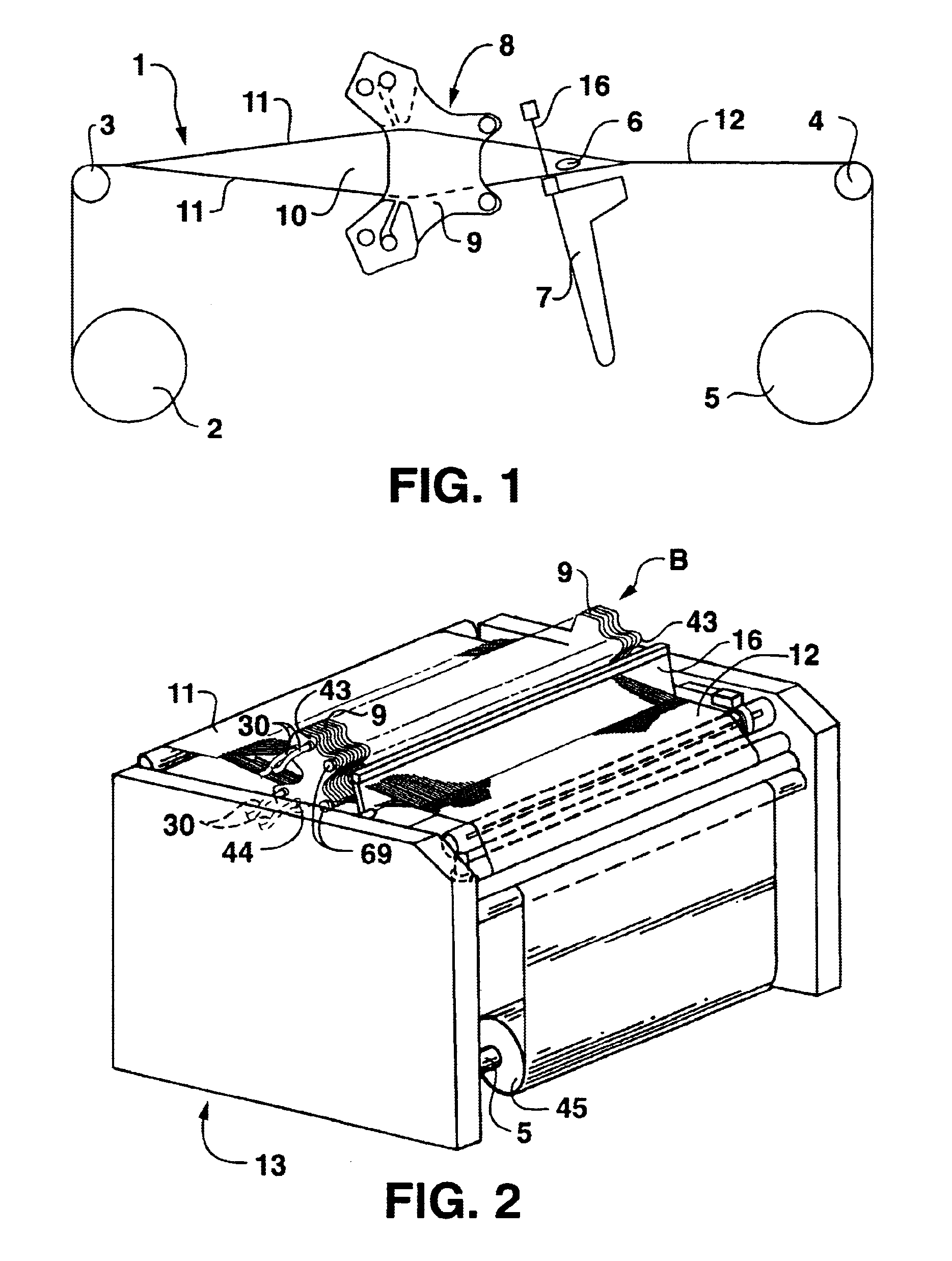
[0037]FIG. 1 and FIG. 2 depict a schematic of a weaving machine generally designated by the reference character 1 with a cut-away view of a preferred embodiment of the present invention and a perspective view of a weaving machine generally designated by the reference character 13 with a preferred embodiment of the present invention installed in it. Warp yarns 11 are drawn over a tension bar 3 in parallel from a warp beam 2 by a take-up roll 5. A fluid is supplied to a shed-forming device generally designated by the ref...


PUM


Abstract

A shed-forming device and a method for using it are provided for creating a shed of warp yarns in a weaving machine. The shed-forming device includes a plurality of yarn separating elements operably disposed to one another within the weaving machine. The yarn separating elements individually separate the warp yarns into operational zones between the yarn separating element. A fluid supply apparatus supplies fluid to the yarn separating elements in the shed-forming device. The yarn separating elements direct the fluid to contact the warp yarns, forcing the warp yarns to form changeable sheds to allow proper weaving.

Description

BACKGROUND OF THE INVENTION[0001]The present invention relates to a method and device for forming a shed of warp yarns for filling insertion within a weaving machine. Shed-forming devices are well known in the art and have been used for thousands of years. Shed-forming devices in the past have been mechanical in nature.[0002]The most common production weaving machines utilize a harness and cam system. The harnesses are frames with a plurality of heddles, each heddle having a warp yarn pass through its eye, thereby allowing the harness to control the warp yarns placed within its heddles. Usually anywhere between two to eight harnesses, each having different warp yarns within its heddles, are used within a weaving machine depending on the complexity of the pattern to be woven. The harness frames rest on oblong or other geometric-shaped cams that rotate off-center on an axis. As the cams turn, the harnesses raise and lower at different intervals within the weaving machine causing the w...

Claims


Application Information

Patent Timeline
Patent Type & Authority Patents(United States)
IPC IPC(8): D03C5/00D03C13/00D03C
CPCD03C13/00
Inventor GENDELMAN, MIKHAILGENDELMAN, FLORA
Owner GENDELMAN MIKHAIL
Why Eureka
Try Eureka