Flexible pipe connecting unit

a flexible pipe and connecting unit technology, applied in the direction of flanged joints, pipe/joints/fittings, sleeves/socket joints, etc., can solve the problems of damage to the sealing surface failure of the rubber body, and failure of the bellows under compression and tension loading, and achieve the effect of stable sealing surface structur

Inactive Publication Date: 2005-09-20
CONTITECH LUFTFEDERSYST
View PDF7 Cites 5 Cited by
  • Summary
  • Abstract
  • Description
  • Claims
  • Application Information

AI Technical Summary

Benefits of technology

[0014]In the pipe connecting unit of the invention, the shearing stresses, which occur in the sealing surface material, are avoided by a cutout in the critical region.
[0016]A form-stable component (for example, metal, thermoplast, et cetera) can be used in the cutout in order to avoid a flowing of the sealing surface material and to introduce a defined compressive stress in the sealing surface. In this way, a stable sealing surface structure is provided.

Problems solved by technology

Flange embodiments having tongue and groove or flanges, which do not engage on the full surface, lead, in a short time, to fissure formations in the sealing surface and therefore to a failure of the rubber body.
Notches of this kind ultimately lead to a destruction of the bellows under compression and tension loading.
Such flanges can also damage the rubber sealing surface.
This does provide a problem-free seal-tight attachment but welding-neck flanges are expensive to manufacture.
However, this is an additional part and therefore constitutes an additional cost factor and makes assembly of the compensator in the pipeline more difficult.
The problem of damage (see FIGS. 4a, 4b or 4c) is more likely to occur when such a flat seal is inadvertently omitted.

Method used


Image

  • Flexible pipe connecting unit
  • Flexible pipe connecting unit
  • Flexible pipe connecting unit

Examples


Embodiment Construction

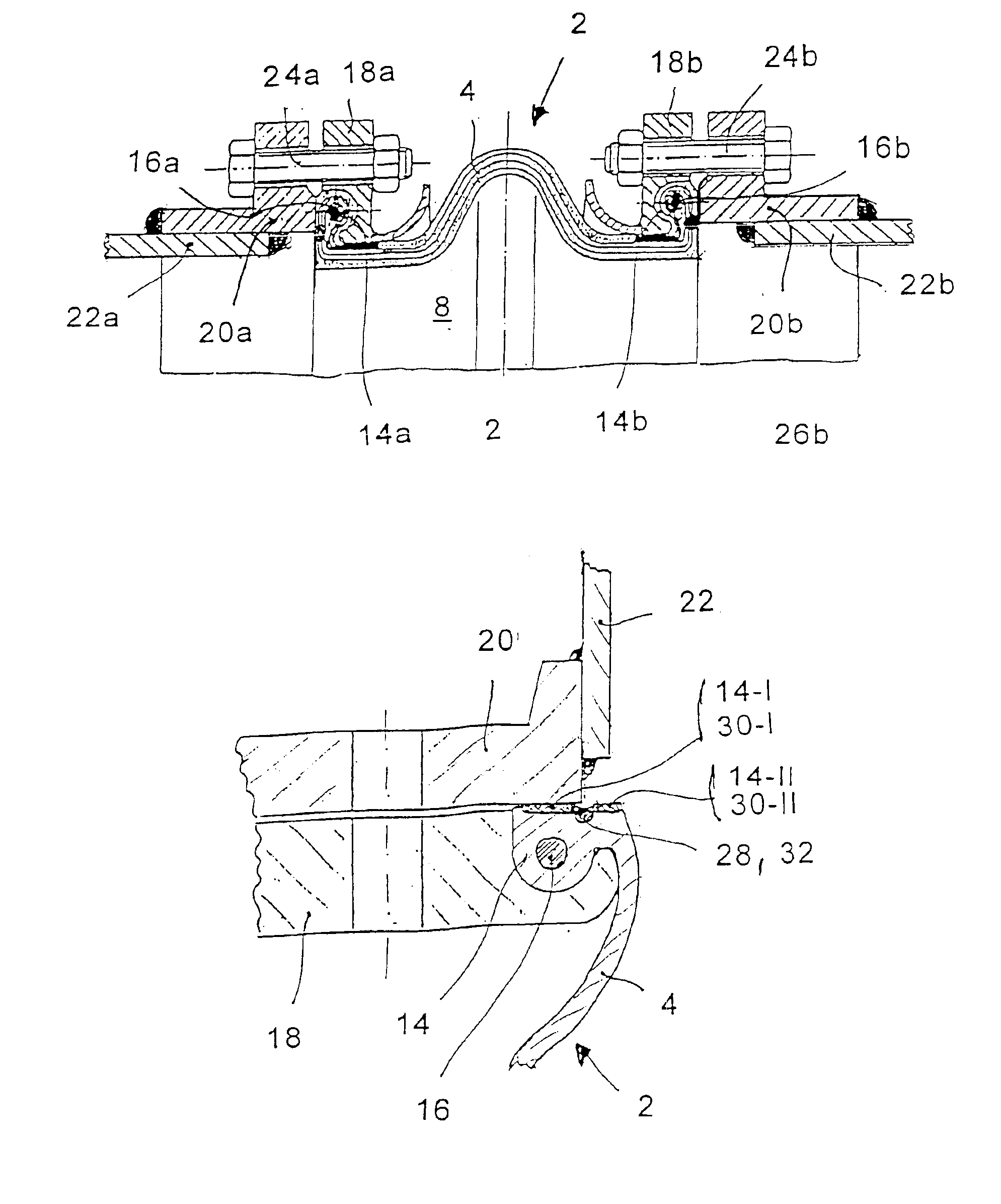
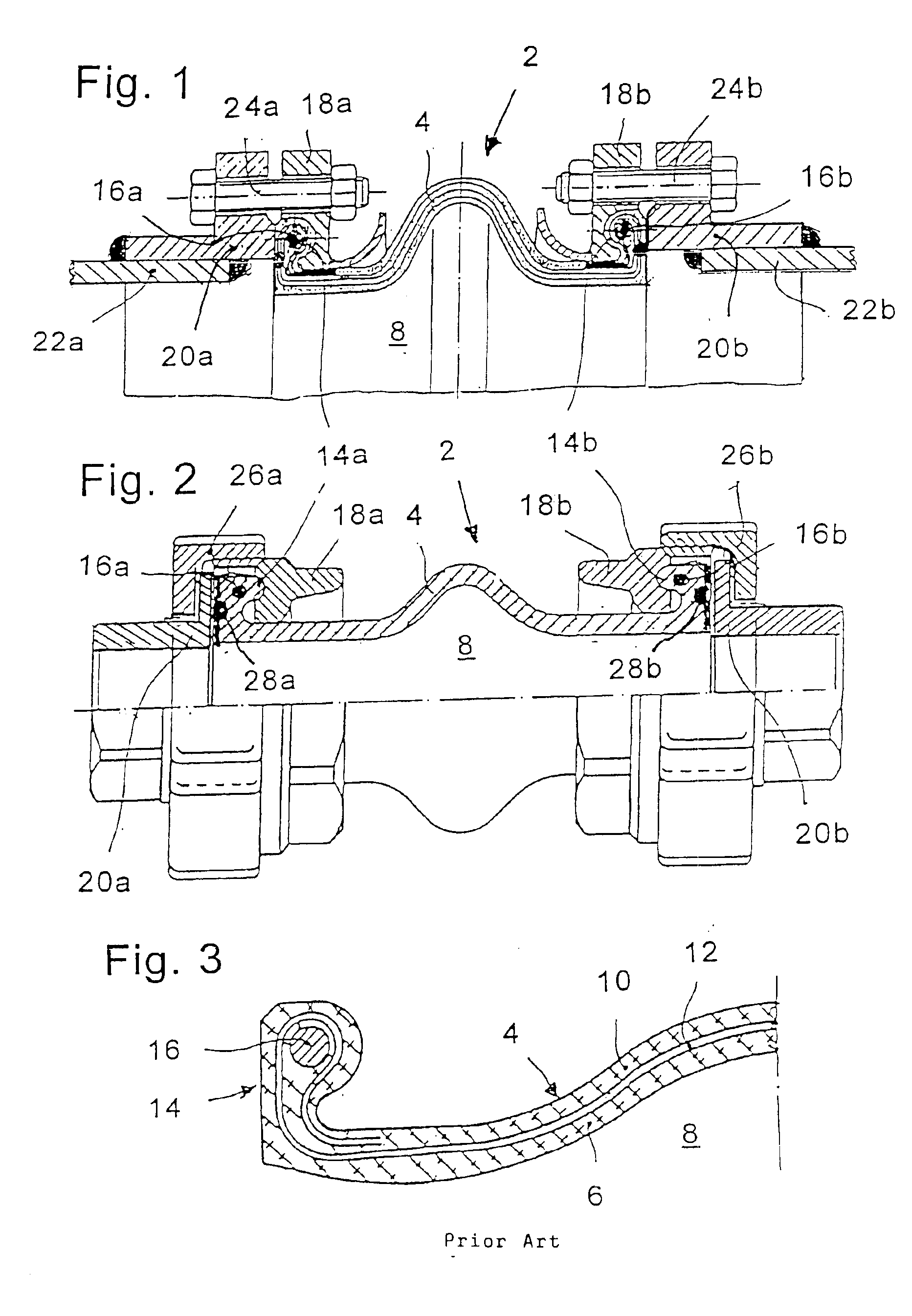
[0024]The pipe connecting unit 2 shown in the drawing is a compensator for use in pipelines subjected to pressure and includes a bellows 4 made of elastic workable material.

[0025]As shown in FIGS. 1 and 2, the bellows 4 is a wavy or cylindrical rubber body having bead-shaped flange collars (14a, 14b) at respective ends thereof with these flange collars being formed so as to extend outwardly. The flange collars (14a, 14b) have respective reinforcements (16a, 16b). The reinforcements need not be realized by a wire but can, for example, also be a spiral spring, hard rubber or thermoplast. An embodiment without separate reinforcement is also an option. Steel flanges (18a, 18b) are mounted before or after vulcanization and are disposed behind the flange collars (14a, 14b). The steel flanges (18a, 18b) are holding flanges and engage and grasp the flange collars (14a, 14b) corresponding thereto.

[0026]The flanges (18a, 18b) are made of carbon steel, special alloy steel or aluminum. Plastic ...


PUM


Abstract

The invention is directed to a flexible pipe connecting unit which includes a part made of elastic workable material. The pipe connecting unit includes a wave-shaped or hose-shaped bellows (4) made of elastomeric material. The bellows (4) has respective projecting flange collars (14; 14 a, 14b) at its respective ends. The flange collars (14; 14a, 14b) preferably are provided with a reinforcement insert (16; 16a, 16b) and annularly-shaped pipe connecting pieces (flanges 18; 18a, 16b) are disposed behind corresponding ones of the flange collars. The pipe connecting unit (2) coacts directly with weld-on flanges as counter flanges (20; 20a, 20b) without additional seals or corresponding joining locations. For this purpose, the end sealing faces of the flange collars (14; 14a, 14b) are partitioned in the radial direction by a peripherally extending slot (28; 28a, 28b). In this way, at least two coaxial concentric annularly-shaped sealing surfaces (14-I, 14-II) are formed. With outer weld-on or slip-on flanges (20; 20a, 20b), only corresponding ones of the outer annular sealing Surfaces (14-I) are in contact engagement and, when the counter flange (20; 20a, 20b) is a welding-neck flange, at least the outer sealing annular surface (14-I) comes into contact engagement. A stabilization ring (32) can be implanted in the slot (28; 28a, 28b) of the flange collar (14; 14a, 14b) between the outer annular sealing surface (14-I) and the inner annular sealing surface (14-II).

Description

FIELD OF THE INVENTION[0001]The invention relates to a flexible pipe connecting unit or so-called compensator made of elastic deformable material having formed-on outwardly projecting end flanges.BACKGROUND OF THE INVENTION[0002]Annular-shaped pipe connecting pieces made of metal function to attach to counter flanges of the pipe ends. The annular-shaped pipe connecting pieces engage behind the end flanges of the pipe connecting unit.[0003]These compensators are utilized in pipelines subjected to thermal load for taking up expansions. Compensators are also used for attenuating vibrations and noise of equipment to be connected such as motors, pumps and the like. Likewise, building in rubber compensators is recommended to effectively interrupt the transmission of structure-borne noise and water-borne noise. Finally, a compensation of assembly inaccuracies can be undertaken with these compensators.[0004]The most varied types of connecting units are known for pipelines. These connecting ...

Claims


Application Information

Patent Timeline
Patent Type & Authority Patents(United States)
IPC IPC(8): F16L51/02F16L51/00F16L27/00F16L27/108F16L55/04
CPCF16L27/108F16L51/024
Inventor FLECK, ANDREASKLUTH, OLAF
Owner CONTITECH LUFTFEDERSYST
Why Eureka
Try Eureka