Ink jet head and ink jet type recording apparatus

a recording apparatus and ink jet technology, applied in printing and other directions, can solve the problems of increasing the total length of driving signal lines, increasing the surface area of the head body b>100/b>, and unavoidable large size of the ink jet head as a whole, so as to improve reliability and yield, reduce the size of the head, and increase the density of the dot

Inactive Publication Date: 2005-09-20
PANASONIC CORP
View PDF4 Cites 10 Cited by
  • Summary
  • Abstract
  • Description
  • Claims
  • Application Information

AI Technical Summary

Benefits of technology

[0016]Thus, since the driver IC is mounted on the head body by face down bonding, with the driver IC facing the head body, it is not necessary to provide a space on the head body for mounting the driver IC, thereby downsizing the head. Moreover, since the signal input terminals of the, actuators are arranged locally between actuator columns, the signal lines are shortened and the head is downsized, unlike in the prior art where the signal input terminals are provided remotely from the actuators. Moreover, since the signal output terminals of the driver IC are locally arranged so as to respectively correspond to the signal input terminals of the actuators, mounting by face down bonding is facilitated.
[0057]Moreover, according to the present invention, at least the driver IC side portion of the head body is made of the same material as the driver IC, or a material whose coefficient of linear expansion is substantially equal to that of the driver IC, whereby when the driver IC is mounted on the head body, the amount of displacement due to thermal deformation can be made substantially equal between the signal input terminals and the signal output terminals, and it is thus possible to prevent the signal input terminals and the signal output terminals from being positionally shifted from each other. Therefore, it is possible to maintain a desirable contact between the signal input terminals and the signal output terminals even if the density of the head increases, thereby improving the reliability and the yield. Moreover, it is possible to suppress deterioration of the ink discharging performance due to thermal deformation.

Problems solved by technology

Thus, there was a problem that the total length of the driving signal lines increases.
Therefore, the surface area of the head body 100 increased, and it was unavoidable for the ink jet head as a whole to be large in size.
Note that such a problem similarly occurs in other arrangements where the driver IC is provided near a side surface of the head body.
Therefore, in a case where the driver IC is mounted on the head body by flip chip bonding, wherein solder bumps, or the like, between terminals are melted by heating, contact failure between terminals was likely to occur due to the difference therebetween in the degree of thermal expansion.
Moreover, even if a desirable connection was obtained when heated, thermal contraction occurred along with the subsequent decrease in temperature, resulting in peeling off of the terminals in some cases.
Thus, even a slight difference in the degree of thermal expansion and thermal contraction between the driver IC and the head body may lead to contact failure between terminals, thereby extremely reducing the yield of the product.
Moreover, the following problem exists which is characteristic of piezo type ink jet heads.
Thus, there was a problem that when the coefficient of linear expansion of the driver IC is substantially different from that of the head body, the rigidity of the actuators changes, thereby making the ink discharging performance instable.
Moreover, a difference in coefficient of linear expansion between the driver IC and the head body might possibly cause warping of the head body.

Method used


Image

  • Ink jet head and ink jet type recording apparatus
  • Ink jet head and ink jet type recording apparatus
  • Ink jet head and ink jet type recording apparatus

Examples


embodiment 1

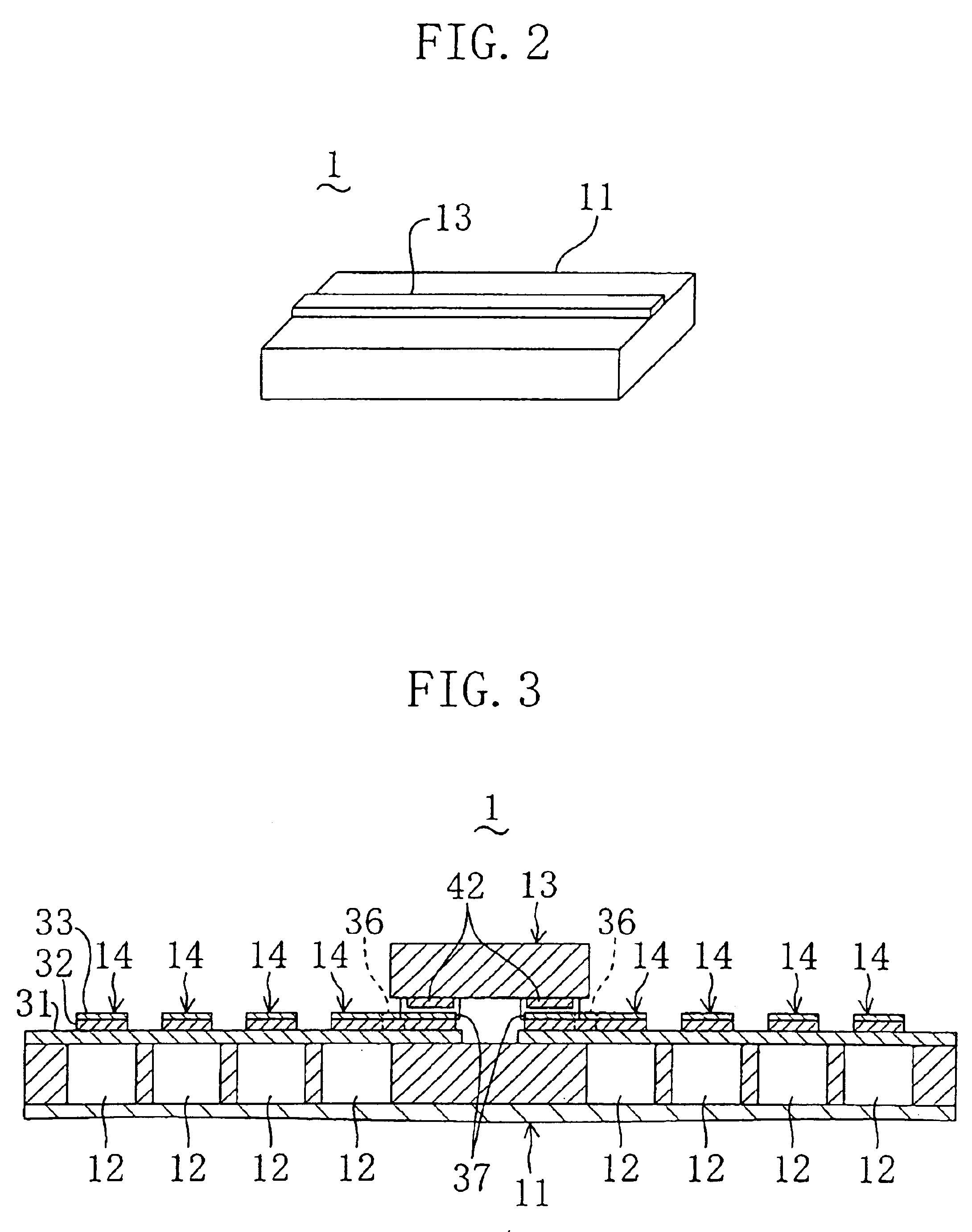
[0082]As illustrated in FIG. 2 and FIG. 3, the ink jet head 1 of Embodiment 1 includes a head body 11 and a driver IC 13. A plurality of nozzles 23 (see FIG. 5) for discharging ink and a plurality of pressure chambers 12 and actuators 14 arranged so as to respectively correspond to the nozzles 23 are formed in the head body 11. The driver IC 13 is made of a silicon (Si), which is a semiconductor material, and the driver IC 13 is provided with a driving circuit (not shown) for supplying a driving signal to the actuators 14. The driver IC 13 is mounted on the head body 11 by flip chip bonding.

[0083]As illustrated in FIG. 2, the head body 11 is formed in a thin-plate-like generally rectangular solid shape having a length of 20 mm, a width of 10 mm and a thickness of about 0.9 mm. On the other hand, the driver IC 13 has a shape elongated in one direction. Specifically, it is formed in a rectangular solid shape having a length of 20 mm, a width of 2 mm and a thickness of 0.4 mm.

[0084]As ...

embodiment 2

[0111]As illustrated in FIG. 14, in the ink jet head 1 , the driver IC 13 is mounted by a face up method, and the terminals of the driver IC 13 and the terminals of the head body 11 are connected together by wire bonding.

[0112]In the present embodiment, the driver IC 13 is attached between the terminals 37 of the right-side actuator columns and the terminals 37 of the left-side actuator columns of the head body 11. In the attachment process, the entire reverse surface of the driver IC 13 may be attached to the head body 11, or may be attached in a dotted matter at two or more positions on the reverse surface. As in Embodiment 1, the driver IC 13 is made of silicon, and at least the first plate 15 of the head body 11 is made of silicon. Note that the configuration of the head body 11 is as that of Embodiment 1.

[0113]Although not shown, the output terminals of the driver IC 13 are provided on the front surface side of the driver IC 13. The output terminals of the driver IC 13 and the ...

embodiment 3

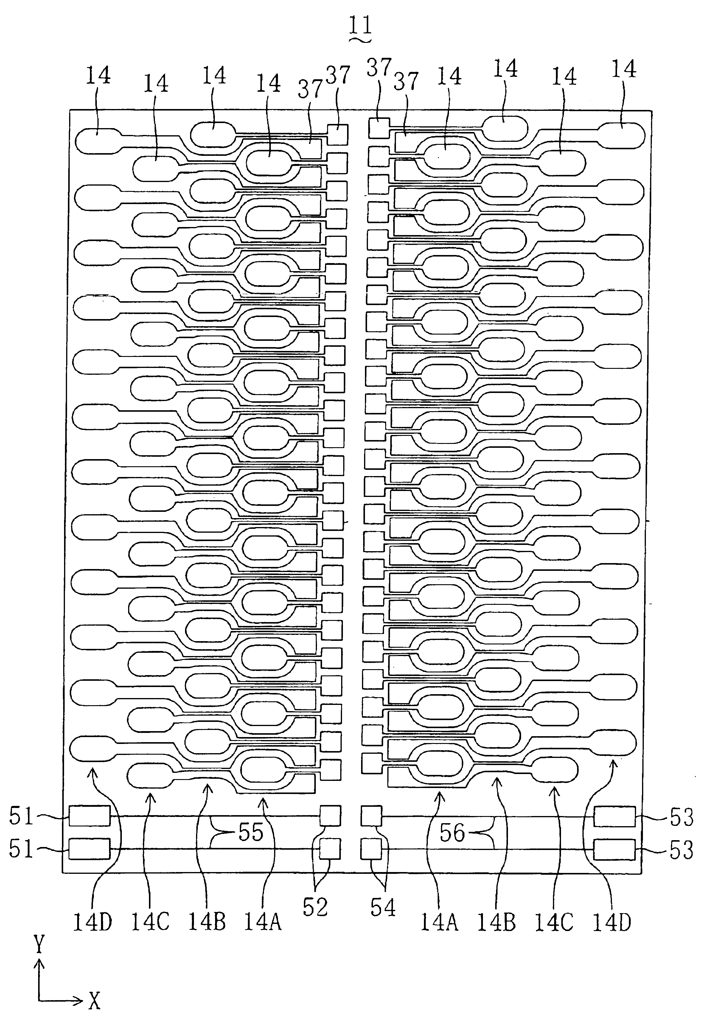
[0115]As the density of the head increases, it is more difficult to provide the conductor 36 of an actuator 14 between other actuators 14 and 14. In view of this, in the ink jet head of Embodiment 3, the arrangement pattern of the actuators 14 and the input terminals 37 is changed so that the conductors 36 are eliminated, as illustrated in FIG. 15.

[0116]Specifically, in the present embodiment, as in Embodiment 1, 8 actuator columns are formed, and an actuator in any actuator column is arranged so as to be shifted in the column direction Y from any other actuator of any other actuator column. Moreover, in the present embodiment, the input terminal 37 of each actuator is arranged near the actuator 14 so as to be continuous with the actuator 14. With such an arrangement, the input terminal 37 is connected directly to the actuator 14, thus eliminating the conductors 36.

[0117]As illustrated in FIG. 16, the output terminals 42 are arranged on the counter surface of the driver IC 13 in a p...


PUM


Abstract

An ink jet head includes a head body (11) which is provided with a plurality of nozzles and a plurality of pressure chambers and actuators (14) respectively corresponding to the nozzles. Input terminals (37) of the actuators (14) are arranged locally between left-side and right-side central actuator columns (14A, 14A). A driver IC (13) is mounted on the head body (11) by flip chip bonding.

Description

TECHNICAL FIELD[0001]The present invention relates to an ink jet head and an ink jet type recording apparatus incorporating the same.BACKGROUND ART[0002]Ink jet heads for recording information by utilizing a piezoelectric effect of piezoelectric elements have been known in the prior art, as disclosed in, for example, Japanese Laid-Open Patent Publication No. 5-18735. An ink jet head of this type is provided with actuators having piezoelectric elements, and is configured to discharge ink through nozzles by the action of the actuators.[0003]Typically, a plurality of pressure chambers to which ink is supplied and a common ink chamber communicated to the pressure chambers are formed separately from each other in a head body. A plurality of nozzles respectively corresponding to the pressure chambers are formed on the reverse side surface of the head body. On the other hand, a vibration plate, a common electrode, a piezoelectric element and a separate electrode are deposited in this order...

Claims


Application Information

Patent Timeline
Patent Type & Authority Patents(United States)
IPC IPC(8): B41J2/14B41J2/045B41J2/05
CPCB41J2/14233B41J2002/1425B41J2002/14459B41J2002/14491
Inventor NAKAMURA, TETSUROHMATSUO, HIROYUKI
Owner PANASONIC CORP
Why Eureka
Try Eureka