Upward-spraying mine well exhaust air heat recovery device and design method thereof

A technology of heat recovery device and design method, which is applied to lighting and heating equipment, direct contact heat exchangers, heat pumps, etc., can solve the problems of large wind blowing water loss, large power consumption of circulating water pumps, and short contact time, etc., to achieve Increase the heat exchange distance and heat exchange time, improve heat recovery efficiency, and increase the effect of heat exchange time

Inactive Publication Date: 2014-04-16
HUNAN UNIV OF SCI & TECH
View PDF7 Cites 6 Cited by
  • Summary
  • Abstract
  • Description
  • Claims
  • Application Information

AI Technical Summary

Problems solved by technology

However, due to the high relative velocity between the air and the spray droplets, choosing too small a droplet size will easily cause the droplets to be blown away, that is, wind blowing water loss; if a larger droplet size is selected, then It is very easy to break the droplets, and the broken droplets will be taken away by the exhaust air flow, resulting in the loss of wind-blown water. Even if a water baffle is installed on the top of the device, the amount of wind-blown water loss is still very considerable; The particle size selection range is narrowed, especially when the head-on wind speed is high, it is even impossible to select the droplet size; from the perspective of selecting the droplet size, there are problems in the selection of the droplet size and the wind blowing water loss; From the perspective of air-water heat and humidity exchange, the contact time between liquid droplets and air in the traditional downspray device is short, and the heat exchange is insufficient, resulting in low thermal efficiency of the device; from the perspective of the power consumption of the circulating water pump, the downspray must The water is raised to at least the height of the diffusion tower itself and above, often as high as 10m or more. In addition, due to the large amount of water sprayed, coupled with the increase in air resistance caused by water spray, the power consumption of the circulating water pump is relatively large

Method used


Image

  • Upward-spraying mine well exhaust air heat recovery device and design method thereof
  • Upward-spraying mine well exhaust air heat recovery device and design method thereof
  • Upward-spraying mine well exhaust air heat recovery device and design method thereof

Examples


Embodiment Construction

[0081] The present invention will be further described in detail below in conjunction with the accompanying drawings and embodiments.

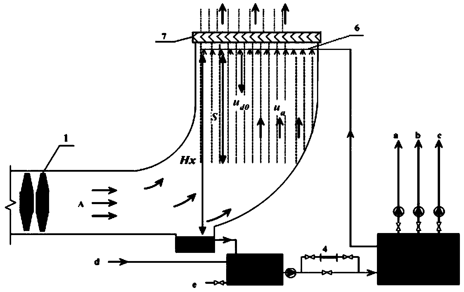
[0082] see figure 1 , which is a schematic diagram of the principle structure of a common mine exhaust heat recovery device, in figure 1 Among them, 1 is the main ventilator, 2 is the sump, 3 is the sedimentation tank, 4 is the water processor, 5 is the heat pump unit, 6 is the pipe row and nozzle, 7 is the water baffle, A indicates the mine return air, a interface Connect the wellbore antifreeze water pipe, the b interface connects the hot water pipe for bathing, the c interface connects the air conditioning water pipe, the d interface connects the waste water pipe of the bathroom, and the e interface connects the sewage device. Hx is the installation height of the nozzle, S is the maximum drop drop height, u a is the face velocity of the air, u d0 is the initial velocity of the droplet. Such as figure 1 As shown, the spraying facilit...


PUM


Abstract

The invention discloses a water-saving, low-resistant and high-efficiency upward-spraying mine well exhaust air heat recovery device and a design method thereof. The upward-spraying mine well exhaust air heat recovery device has the technical points that the device comprises a water baffle, a water collection tank, a sedimentation tank, a water treatment device, a heat pump machine unit, a pipe row and a spraying nozzle, and is characterized in that the row pipe and the spraying nozzle are arranged on the bottom part in a diffusion tower, and the spraying nozzle sprays water upward; in the situation that the liquid droplets sprayed by the spraying nozzle are not broken, are not blown away and are not suspended, the distance H between the spraying nozzle and the top end of the diffusion tower is greater than and close to the maximum rising height Z of the liquid droplets sprayed by the spraying nozzle; various parameters of the device are optimized respectively by utilizing the newton's second law and a numerical simulation method. The heat exchange distance and the heat exchange time between the liquid droplets and exhaust air are increased by the optimized device; the kinetic energy of the exhaust air of a mine well is utilized effectively; the heat recovery efficiency of the device is improved. Water is not required to be sprayed downward after being conveyed to the top part by the device, but is sprayed upward directly, so that the power consumption of a water pump is reduced.

Description

technical field [0001] The invention belongs to the technical field of mine exhaust heat recovery, and in particular relates to a water-saving, low-resistance, high-efficiency upspray type mine exhaust heat recovery device and a design method thereof. Background technique [0002] Mine exhaust air heat recovery devices generally arrange spraying facilities on the top of the diffusion tower, and spray cold water downward to recover exhaust air heat energy. However, due to the high relative velocity between the air and the spray droplets, choosing too small a droplet size will easily cause the droplets to be blown away, that is, wind blowing water loss; if a larger droplet size is selected, then It is very easy to break the droplets, and the broken droplets will be taken away by the exhaust air flow, resulting in the loss of wind-blown water. Even if a water baffle is installed on the top of the device, the amount of wind-blown water loss is still very considerable; The parti...

Claims


Application Information

Patent Timeline
Patent Type & Authority Applications(China)
IPC IPC(8): F28C1/14F28F25/06F25B27/02F25B30/06
CPCY02A30/274Y02P80/15
Inventor 王海桥崔海蛟陈世强李轶群李永存贾腾赵杰章晓伟
Owner HUNAN UNIV OF SCI & TECH
Why Eureka
Try Eureka