

Linear motor and linear compressor
a linear compressor and linear motor technology, applied in the direction of positive displacement liquid engine, piston pump, magnetic circuit shape/form/construction, etc., can solve the problems of increasing the overall cost of the motor, reducing the life of the motor, and reducing the operation efficiency of the motor, so as to reduce the mass of magnetic materials, increase the operating efficiency, and reduce the cost
- Summary
- Abstract
- Description
- Claims
- Application Information
AI Technical Summary
Benefits of technology
Problems solved by technology
Method used
Image

Examples
exemplary embodiment 1
(Exemplary Embodiment 1)
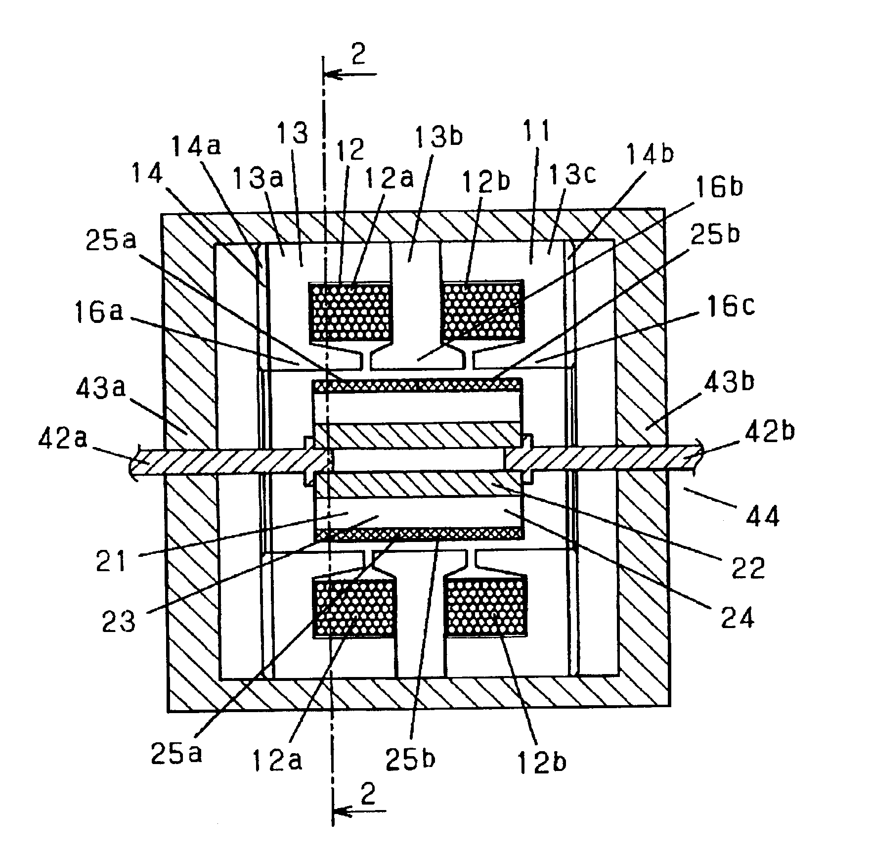
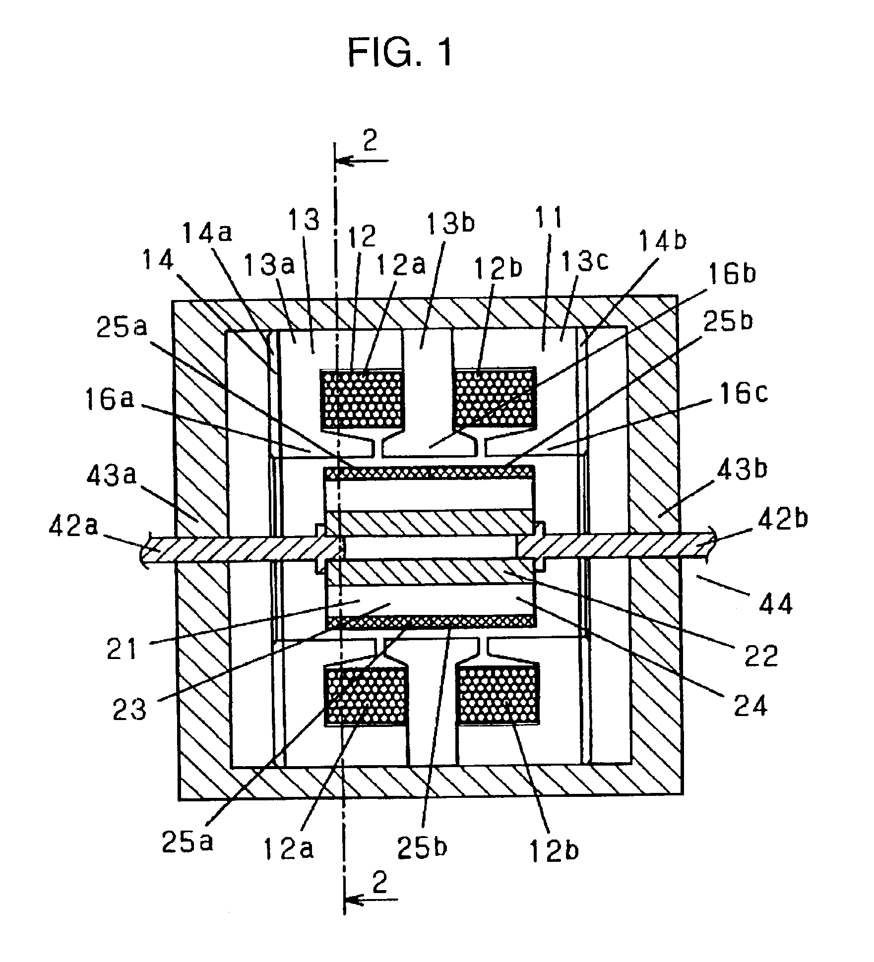
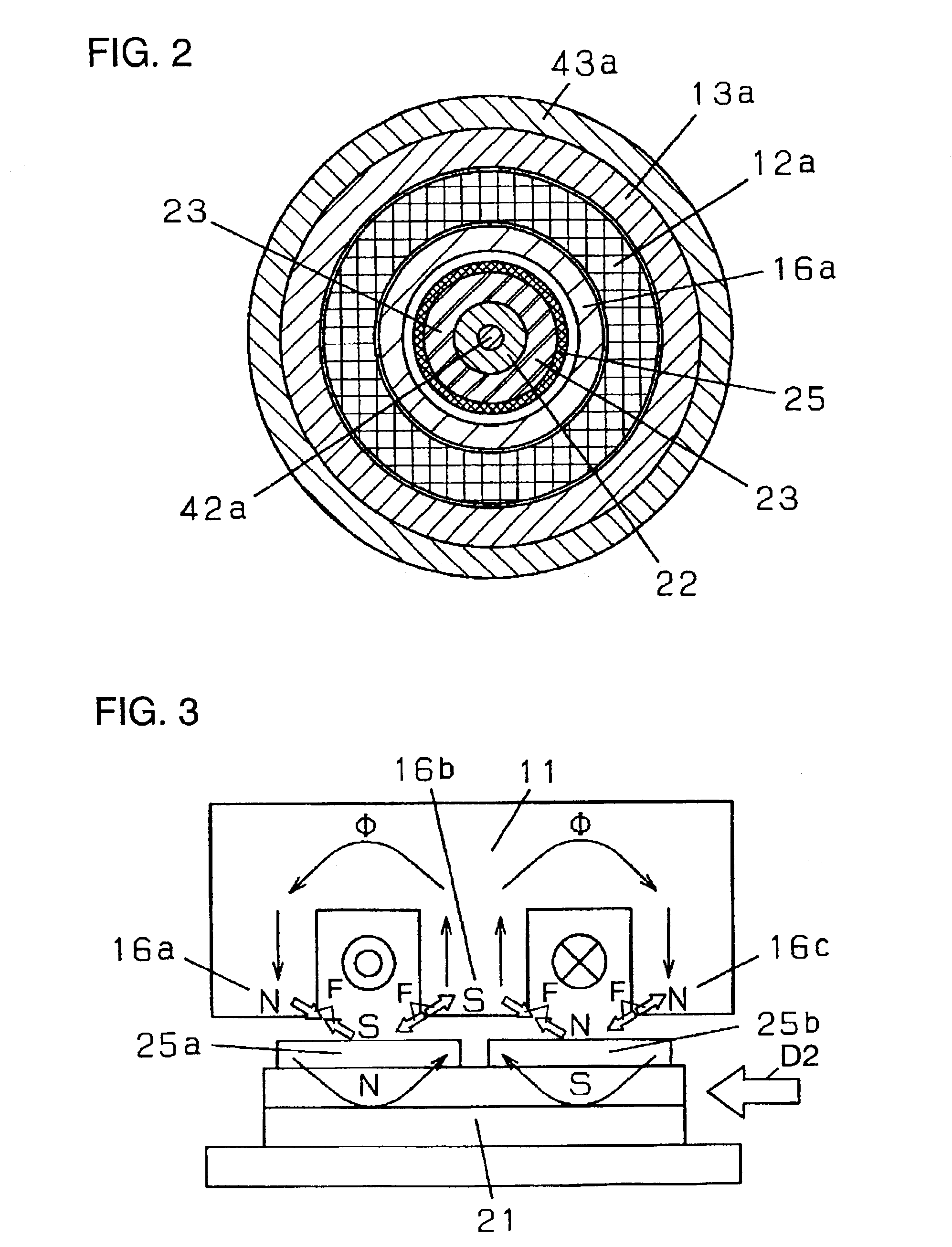
[0024]FIG. 1 is a cross sectional side view of a linear motor according to exemplary embodiment 1 of the present invention. FIG. 2 is a cross sectional view of the linear motor at a line 2—2 of FIG. 1. FIG. 3 is a schematic view illustrating an operational principle of the linear motor. FIG. 4 is a schematic view illustrating electric currents flowing in the linear motor.
[0025]In this description, the linear motor employs, for example, a magnet wire as a wire for generating a magnetic force.
[0026]A stator 11 of the linear motor has a substantially cylindrical shape and includes two magnetic wires 12 wound like rings and a stator core 13. The core has three magnetic poles developed separately on its inner side and is configured to have the magnetic wires 12 accommodated therein.
[0027]The stator core 13 is made of sheets of silicon steel, such as JIS C2352 non-directionally electromagnetic steel. The sheets are magnetically non-directional, have high magnetic p...
exemplary embodiment 2
(Exemplary Embodiment 2)
[0052]FIG. 5 is a cross sectional view of a linear motor according to exemplary embodiment 2 of the present invention. FIG. 6 is a cross sectional view of the liner motor at a line 6—6 of FIG. 5. FIG. 7 is an enlarged view of a primary part of the linear motor. FIG. 8 is a schematic view showing an operational principle of the linear motor.
[0053]A stator 71 of the linear motor includes two magnetic wires 12 previously would like rings, a stator core 72, an outer stator core portion 73, and end plates 14, and is disposed at the outside of a mover 12.
[0054]Both the outer stator core portion 73 and the stator core 72 consisting of three portions 72a, 72b, and 72c are made of sheets of silicon steel, such as JIS C2353 directionally electromagnetic steel, which are directional and have high magnetic permeability, and are arranged to extend radially about their axis.
[0055]The magnetic wire 12a is accommodated between the stator core portions 72a and 72b, while the ...
exemplary embodiment 3
(Exemplary Embodiment 3)
[0061]FIG. 9 is a cross sectional view of a linear compressor according to exemplary embodiment 3 of the present invention. The linear motor 80 includes a stator 71 and a mover 21. The stator 71 has a substantially cylindrical shape and includes two magnetic wires 12 wound like rings. The mover 21 including a magnet 25 on its outer side has a substantially cylindrical shape being coaxial with the stator 71, and is accommodated in the interior space of the stator 71 for oscillating movement along the common axis. A frame 81 including a cylinder 82 supports a shaft 42d and holds the outer side of the stator 71. The cylinder 82 has an interior space coaxial with the linear motor. A cylindrical piston 83 is joined to the distal end of a shaft 42c and is accommodated in the cylinder 82 for oscillating movement. The cylinder 82 and the piston 83 configures a compression chamber 84. The mover 80 of the linear motor 80, the shafts 42c and 42d, and the piston 83 confi...
PUM
 Abstract
Description
Claims
Application Information