
Digital-to-analog converter having error correction

a digital-to-analog converter and error correction technology, applied in digital-analog converters, physical parameters compensation/prevention, instruments, etc., can solve the problem that the nonideal behavior of current sources is the important limiting factor affecting the linearity of current-steering dacs, and achieve the effect of cheap on-chip implementation

Inactive Publication Date: 2005-09-20
INFINEON TECH AG
View PDF8 Cites 20 Cited by
  • Summary
  • Abstract
  • Description
  • Claims
  • Application Information

AI Technical Summary

Benefits of technology

The invention provides a low-complexity model for compensating errors in a digital-to-analog converter (DAC) that allows for a relatively cheap on-chip implementation. The model takes into account the fact that errors in the DAC are caused by a combination of a desired value, an error, and a relative step error. The invention proposes a technique for modifying the input values to the DAC to reduce errors and achieve a more accurate output. The technical effects of the invention include improved accuracy and efficiency of DACs in error compensation systems.

Problems solved by technology

Besides e.g. component mismatch, an important limiting factor affecting the linearity of current-steering DACs is the nonideal behavior of current sources and switches due to parasitic resistances and capacitances.

Method used


Image

  • Digital-to-analog converter having error correction
  • Digital-to-analog converter having error correction
  • Digital-to-analog converter having error correction

Examples


Embodiment Construction

The Ideal Current-steering DAC

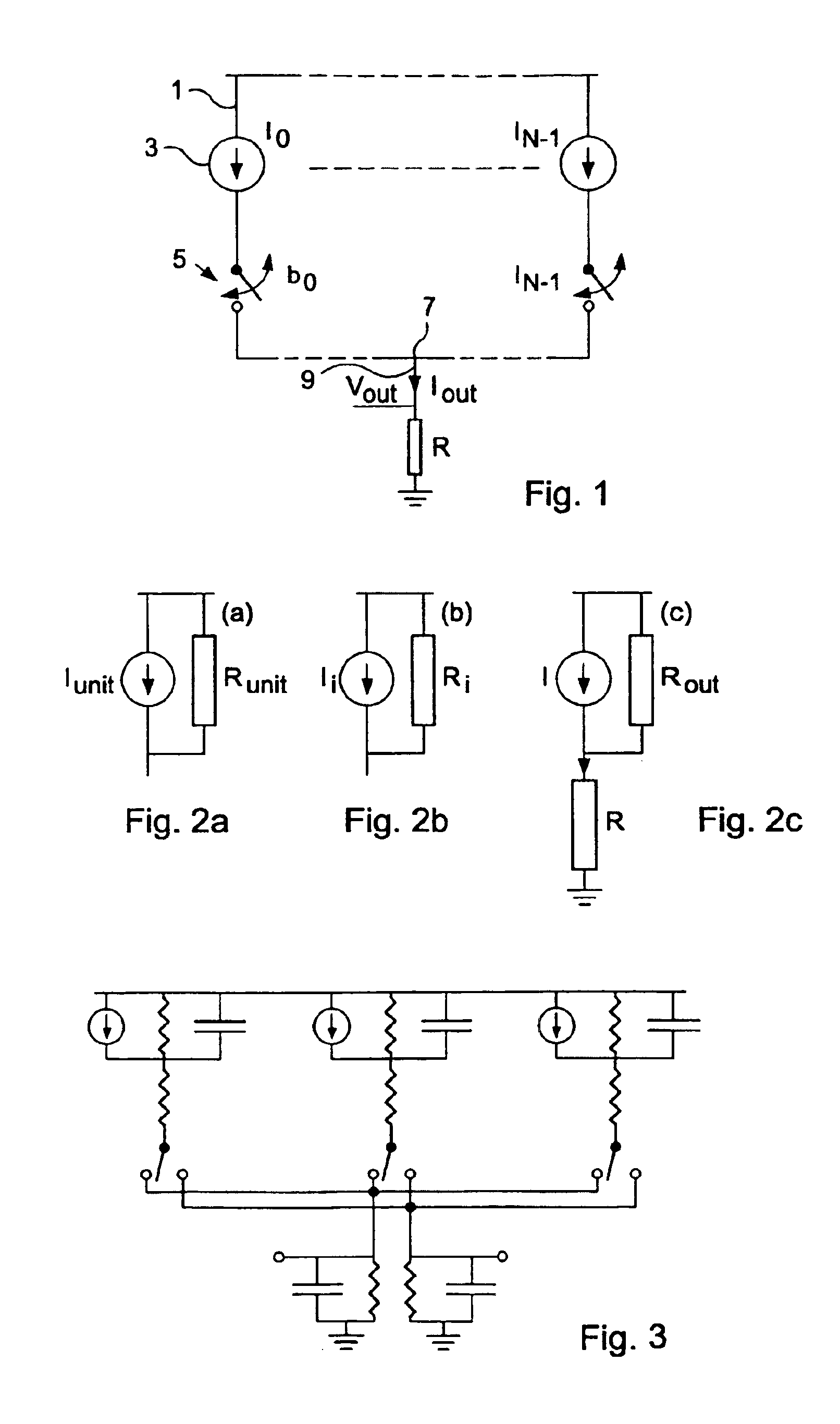
[0025]A schematic circuit diagram of an ideal current-steering digital-to-analog converter is shown in FIG. 1. In N parallel lines 1 current sources 3 providing current intensities I0, I1, . . . , IN are connected. Controlled switches 5 are also connected in the lines 1 that at their output ends are connected to a common node 7 also coupled to an output line 9 in which the output current intensity Iout is provided to a load or termination resistance R. The output voltage at the node 7 is Vout. The switches 5 are controlled by input electrical signals representing a digital input vector X=[bN−1, . . . , b0], which in turn represents an integer value X=∑i=0N-1⁢bi·wi,

where wi is the weight of bi, the wi in most cases being integer numbers, and bi∈{0,1}. In the following the letter X will be used to represent both the integer value and the vector, since the risk for confusion is small. The desired operation for the DAC is to construct an output current, or ...


PUM


Abstract

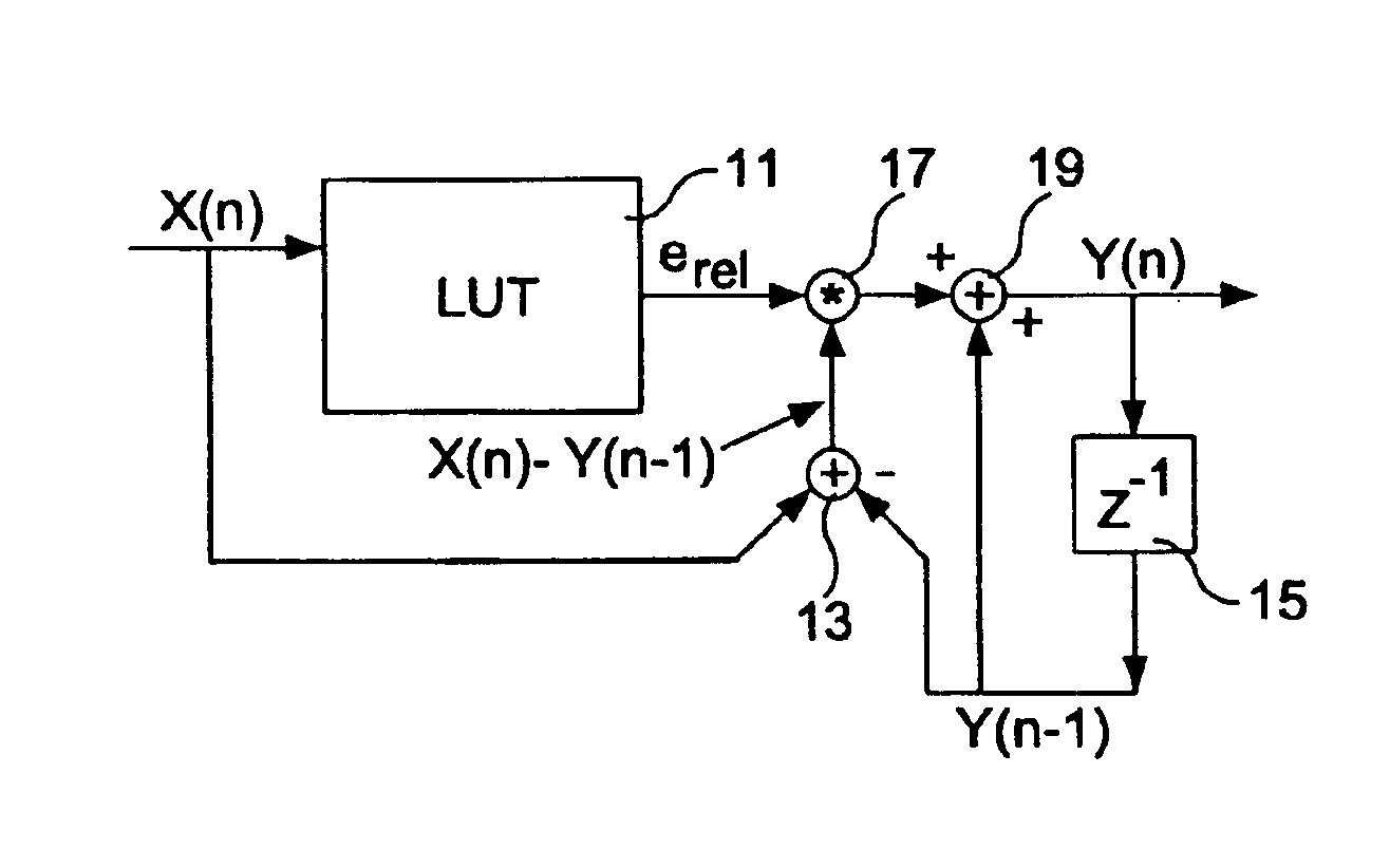
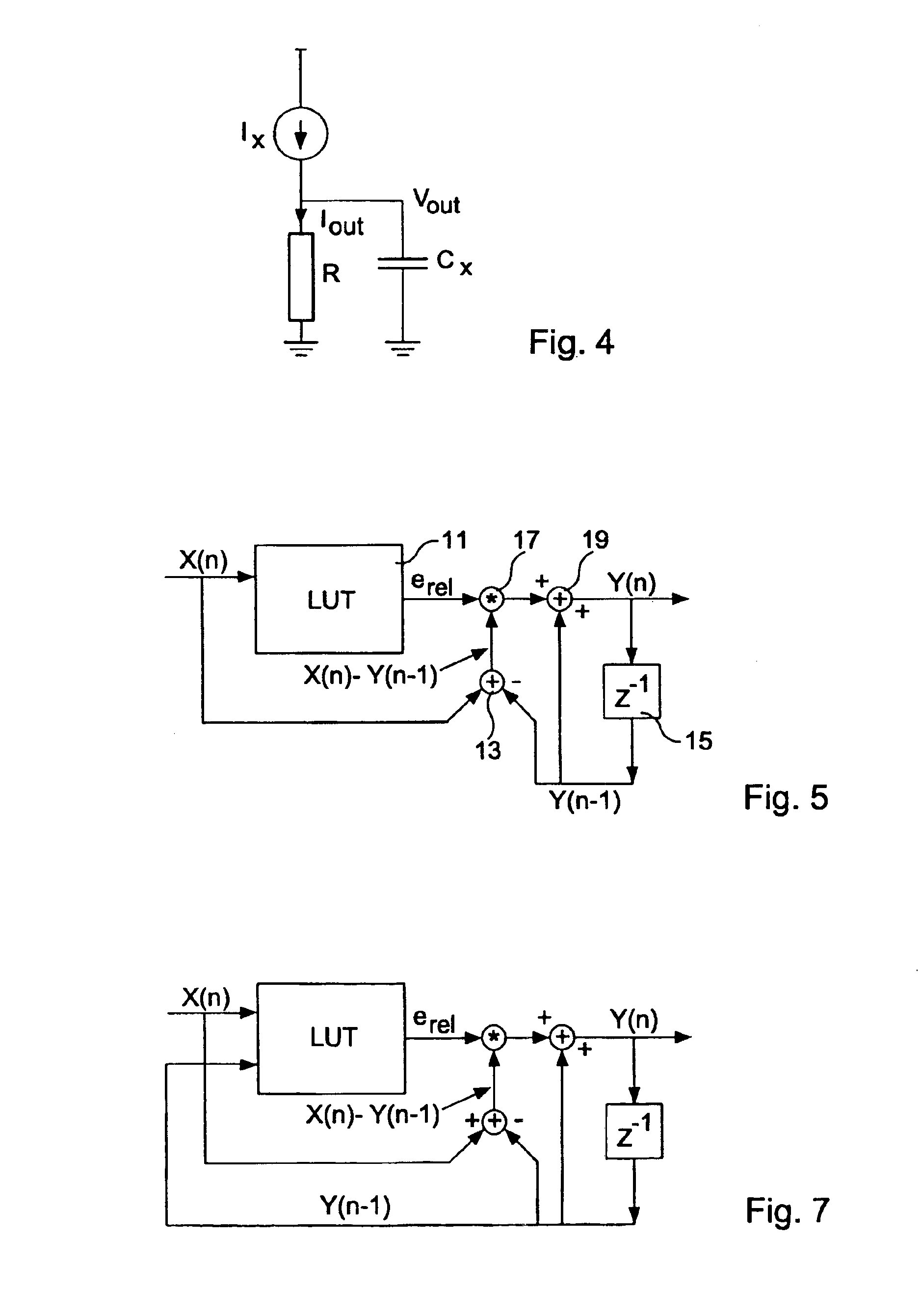
The values X(n) input to a current-steering digital-to-analog converter (49) are modified (41) before the actual conversion to compensate for conversion errors of the digital-to-analog converter. The input values are modified according to a model (43) of the digital-to-analog converter in which each output value of the digital-to-analog converter Y(n) is a sum of a desired value directly proportional to the respective input value and an error. The error is a product of the settled output value, i.e. the difference between the desired value and the previous output value Y(n−1) actually provided by the digital-to-analog converter, and a relative step error that is a function only of the respective input signal and is stored in a table. The relative step error can be a function also of the previous output signal and of the previous input signal. This model has a low complexity and is suitable for on-chip implementation.

Description

CROSS-REFERENCE TO RELATED APPLICATION[0001]This application is a continuation of copending International Application No. PCT / SE03 / 00595 filed Apr. 14, 2003 which designates the United States, and claims priority to Swedish application no. 0201272-2 filed Apr. 26, 2002.TECHNICAL FIELD OF THE INVENTION[0002]The present invention relates to current-steering digital-to-analog converters (DACs) having error correction.BACKGROUND[0003]Digital-to-analog converters are used in many electronic devices providing an electrical output signal or a physical non-electrical output signal. Such devices include e.g. electronic digital devices having antennas for transmitting electromagnetic waves or for providing audible signals such as mobile telephones and CD players. A DAC receives at periodically repeated times an input digital signal and provides at times somewhat after said repeated times an output signal, such as an electric voltage or current, having a magnitude that should be proportional t...

Claims


Application Information

Patent Timeline
Patent Type & Authority Patents(United States)
IPC IPC(8): H03M1/06H03M1/10H03M1/66H03M1/74
CPCH03M1/1033H03M1/742
Inventor ANDERSSON, OLAWIKNER, JACOB
Owner INFINEON TECH AG
Learn More