Power protection device

Inactive Publication Date: 2005-09-20
ELECTRONICS SYST PROTECTION
View PDF3 Cites 38 Cited by
  • Summary
  • Abstract
  • Description
  • Claims
  • Application Information

AI Technical Summary

Benefits of technology

[0014]Supply system wiring faults, such as loss of ground continuity, can cause operational problems for electronic equipment; especially when the equipment is part of a network. In addition, loss of ground continuity increases the risk of electrical shock for equipment operators. The device according to the present invention responds to a variety of single and multiple wiring fau

Problems solved by technology

Supply system wiring faults, such as loss of ground continuity, can cause operational problems for electronic equipment; especially when the equipment is part of a network.
In addition, loss of ground continuity increases the risk of electrical shock fo

Method used


Image

  • Power protection device
  • Power protection device
  • Power protection device

Examples


Embodiment Construction

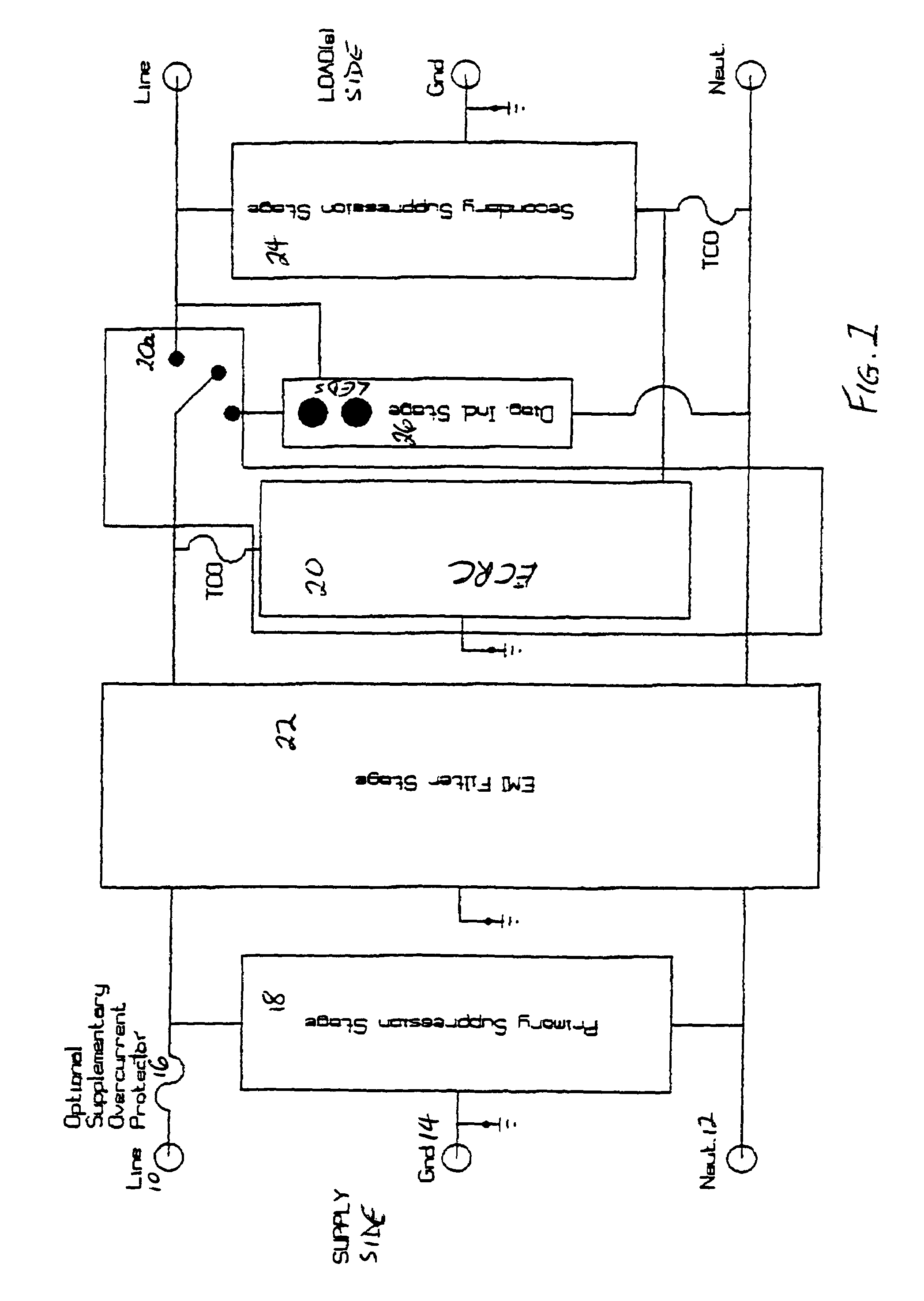
[0039]FIG. 1 is a block diagram of the preferred embodiment of the invention. The illustration includes supply side line 10, neutral 12, and ground 14 terminals that connect to the line, neutral, and ground contacts, respectively, of the supply system (not shown).

[0040]An optional supplementary over-current protector 16 (a thermal circuit breaker or fuse), is connected in series with line conductor 10, and is used to protect the device and connected equipment (not shown) from over-current conditions such as those caused by a connected equipment fault.

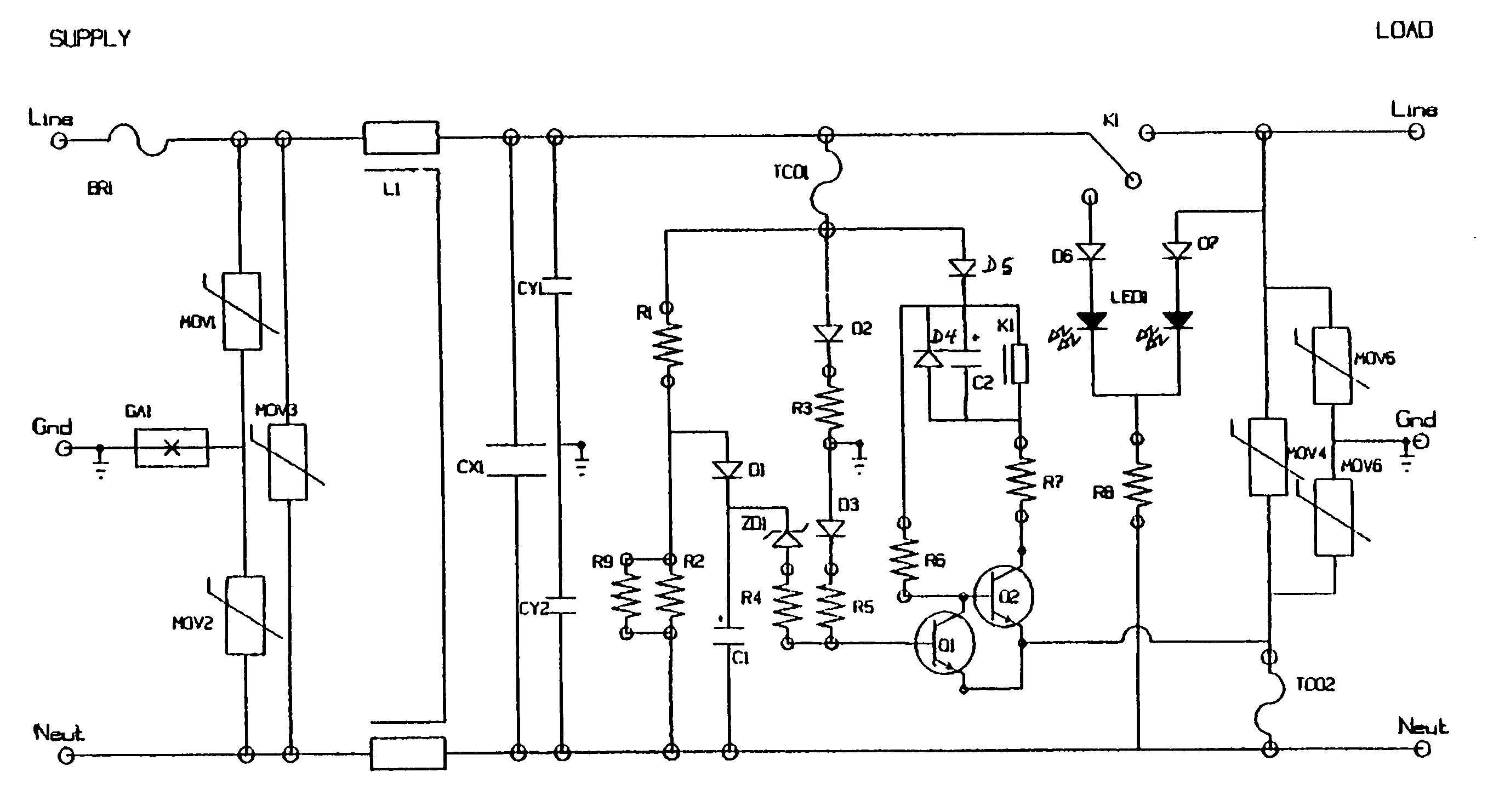
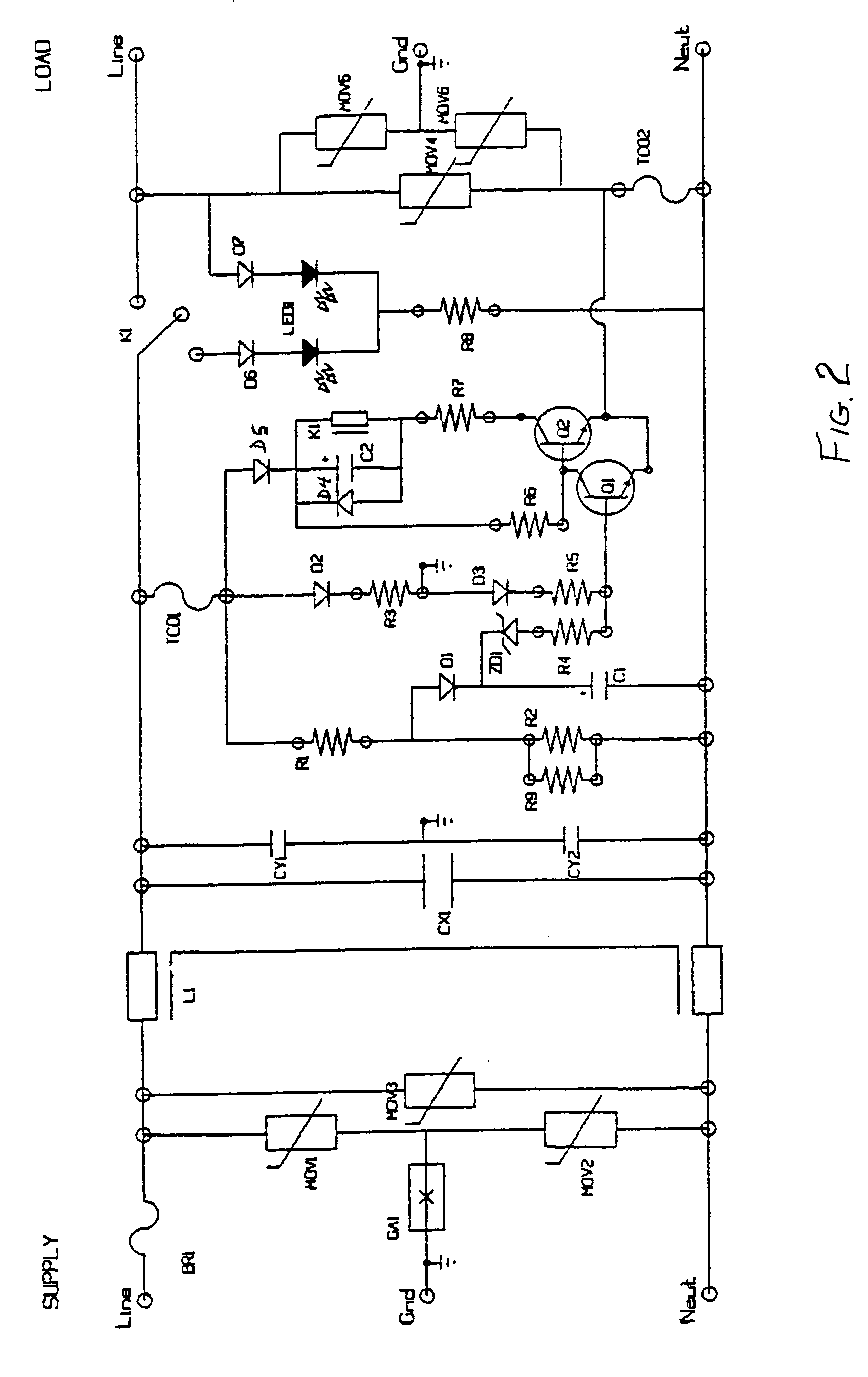
[0041]A primary suppression stage, which utilizes both MOV and GDT components as would be known to one skilled in the art, is connected across the line, neutral, and ground conductor pairs on the load side of supplementary overcurrent protector 16, and is used as primary transient protection for the ECR circuit 20 and connected equipment. Primary suppression stage 18, as well as EMI filter stage 22 and ECR circuit 20, is designed to wit...


PUM


Abstract

A power protection device protects electronic equipment from AC supply system disturbances. An electronically controlled relay circuit passes power to connected equipment if the electrical supply system, to which the equipment is connected, is properly wired for continuity and correct polarity of line, neutral, and ground conductors, and the line voltage is within twenty-five percent of nominal levels. Thermal cut-offs are used as a back-up to the over-voltage protection provided by the electronically controlled relay circuit. These thermal cut-offs are connected in a way that when either or both trip, the relay of the electronically controlled relay circuit is de-energized and power is disconnected to the device output stage and connected equipment.

Description

FIELD OF THE INVENTION[0001]The invention relates to devices for protecting electronic equipment from power-line disturbances such as pulsed and continuous electromagnetic interference (EMI), as well as extended over-voltages.BACKGROUND OF THE INVENTION[0002]For more than 20 years, companies have been developing and marketing products that are connected between the AC supply system and electronic equipment, in an attempt to protect the connected electronic equipment from a variety of power-line disturbances. Currently, many designs incorporate hybrid technology that combines both filter circuits, such as passive LC filter networks, and suppressor technologies, such as metal oxide varistors (MOVs), and gas discharge tubes (GDTs), in an attempt to protect against a broader range of disturbances than either technology on its own.[0003]In order to divert common mode disturbances away from connected equipment, all protective products, regardless of technology, (i.e. filter, suppressor, h...

Claims


Application Information

Patent Timeline
IPC IPC(8): H02H3/00H02H5/10H02H9/04H02H11/00
CPCH02H5/105H02H9/042H02H11/002H02H11/006
Inventor BILLINGSLEY, RICHARD J.
Owner ELECTRONICS SYST PROTECTION
Why Eureka
Try Eureka