Encoding and decoding ultra-wideband information

a technology of ultra-wideband information and encoding, applied in the field of ultra-wideband communication system and system, can solve the problems of no longer matching the negative pulse with the positive pulse, and the remedy will not substantially improve the accuracy of the transmitted information

Inactive Publication Date: 2005-09-20
INTELLECTUAL VENTURES HLDG 73
View PDF31 Cites 70 Cited by
  • Summary
  • Abstract
  • Description
  • Claims
  • Application Information

AI Technical Summary

Benefits of technology

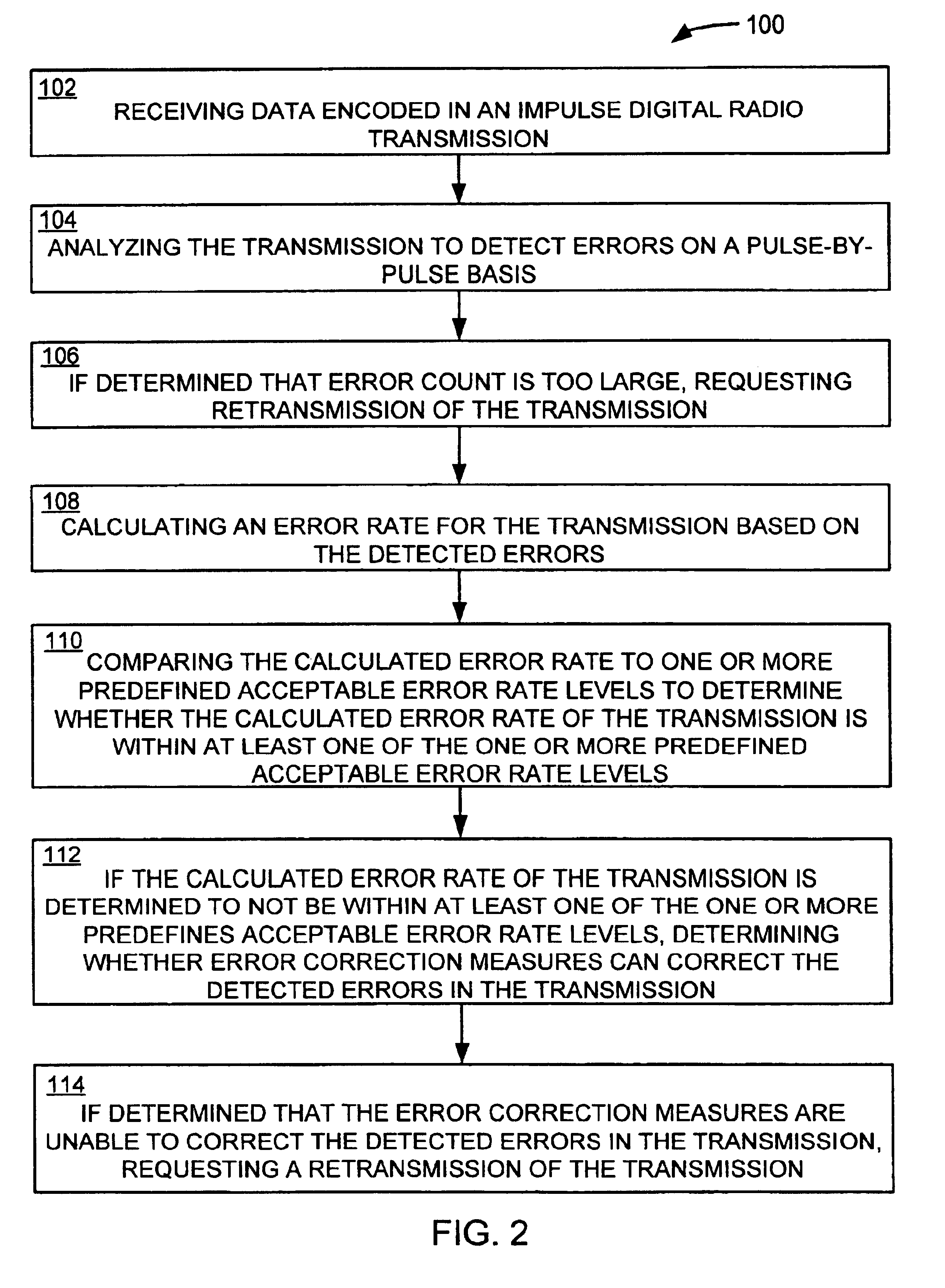
[0006]The present invention alleviates to a great extent the disadvantages of conventional apparatus and method of encoding and decoding transmitted information by providing a system and method for encoding and decoding ultra-wideband transmissions that detects errors in the transmission before the entire transmission is received.
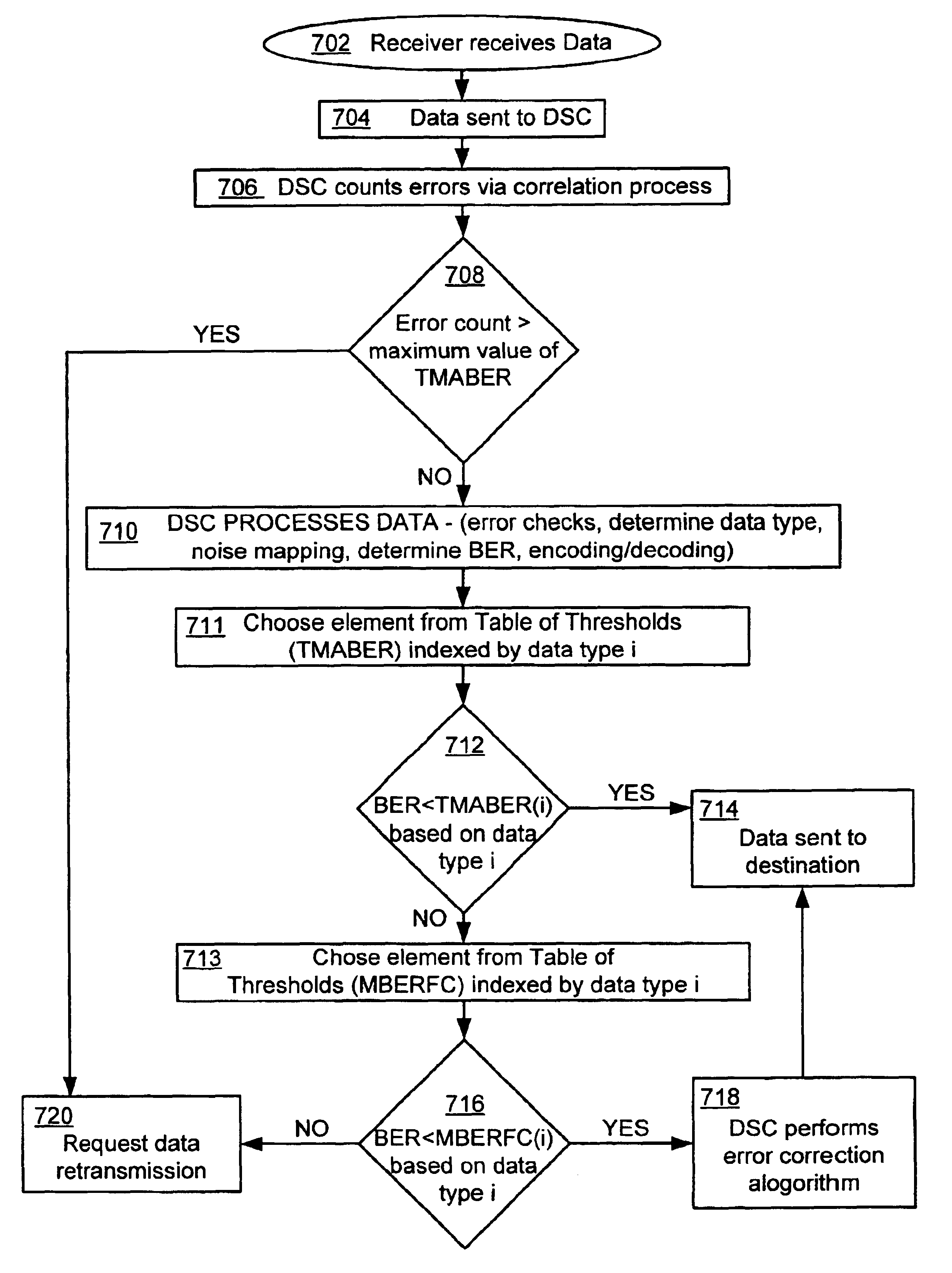
[0008]An ultra-wideband transmitting source is provided to transmit information over a plurality of frames, each frame having a known time duration. Each frame includes at least one bipolar pulse pair that comprises a positive pulse and a corresponding negative pulse. Each frame may be partitioned into a positive data window and a negative data window. The encoding of the transmission is achieved by positioning the positive pulse within the frame and, preferably, within the positive data window. To facilitate efficient error detection, the corresponding negative pulse is positioned within frame and preferably, within the negative data window. The relative position of the negative pulse in the negative data window is the same as the relative position of the positive pulse in the positive data window. Furthermore, the negative pulse has the same pulse width and an equal, but opposite, amplitude. Thus, if the transmission is corrupted by external signals, the negative pulse will no longer match the positive pulse. When a frame is received at a receiver, error detection occurs by correlating the positive pulse in the positive data window with the negative pulse in the negative data window. Thus, errors are counted on a per frame or per pulse pair basis. The error count provides an indication of the degree of degradation of the transmitted information. If the error count exceeds an error threshold, then the receiver requests that the transmitting source re-transmit the information. It is advantageous that an indication of the degree of degradation of the transmitted information is achieved before the transmission is entirely received.

Problems solved by technology

Thus, if the transmission is corrupted by external signals, the negative pulse will no longer match the positive pulse.
Moreover, the calculated error rate may indicate that the information is so corrupted that the error correction remedies will not substantially improve the accuracy of the transmitted information.

Method used


Image

  • Encoding and decoding ultra-wideband information
  • Encoding and decoding ultra-wideband information
  • Encoding and decoding ultra-wideband information

Examples


Embodiment Construction

[0026]When utilizing ultra-wideband pulse technology, typically not more than 10% of the available 1 ns pulse windows are available due to multi-path reflections and other physical constraints sometimes present in ultra-wideband technology. A 10% utilization of the available time windows results in a data rate or channel capacity of 100 Mbits per second, using 1 ns pulse windows. The remaining 90% of the pulse windows is not used and is therefore considered “inactive” due to these constraints. The challenge then becomes how to best utilize that 10% of “active” pulse windows. By using pulse position modulation (“PPM”) in conjunction with these “inactive” windows, the inactive windows may be utilized to further define digital data, giving an increase in total bandwidth, with no associated increase in the “active” pulses emitted.

[0027]The present invention contemplates that, when using a non-resonant antenna to transmit ultra-wideband pulses, positive pulses emitted by the antenna have...


PUM


Abstract

A system and a method for encoding and decoding ultra-wideband information are provided. An ultra-wideband transmission is encoded by positioning bipolar pulse pairs. The bipolar pulse pairs assist in detecting errors in the ultra-wideband transmission, before the entire transmission has been received. The transmission is analyzed for errors and an error rate is calculated. The calculated error rate is compared to one or more predefined acceptable error rate levels to determine whether the calculated error rate of the transmission is within at least one of the predefined acceptable error rate levels.

Description

[0001]Priority is claimed from U.S. Provisional Patent Application Ser. No. 60 / 255,469, filed on Dec. 14, 2000, entitled “Ultra-Wideband Communication System and Method”, which is incorporated herein by reference in its entirety.FIELD OF THE INVENTION[0002]The present invention generally relates to a system and a method of wireless communication and, more particularly, to a system and a system and method of ultra-wideband communication.BACKGROUND OF THE INVENTION[0003]Ultra-wideband transmission of information typically operates in highly populated frequency ranges. Typically, ultra-wideband communications (e.g., impulse radio communications) employ pulses of very short duration on the order of nanoseconds or picoseconds, for example. However, signals of such short duration often must contend with a variety of natural and synthetic noise signals resulting in signal cancellation, amplification or interference.[0004]Furthermore, the transmission errors can be compounded by conventiona...

Claims


Application Information

Patent Timeline
Patent Type & Authority Patents(United States)
IPC IPC(8): G01S13/00G01S13/87H04L1/08H04L1/16H04B1/69H04B17/00H04L1/18H04L1/20H04B1/10H04Q7/38H04Q7/34H04L25/34H04W28/04
CPCG01S13/878H04B1/1027H04B1/7174H04B1/7176H04L1/08H04B17/309H04L1/1829H04L25/4902H04L1/203H04W28/04H04L1/1816
Inventor SANTHOFF, JOHN H.ARRIETA, RODOLFO T.
Owner INTELLECTUAL VENTURES HLDG 73
Why Eureka
Try Eureka