Image forming apparatus

Inactive Publication Date: 2005-09-20
CANON KK
View PDF5 Cites 2 Cited by
  • Summary
  • Abstract
  • Description
  • Claims
  • Application Information

AI Technical Summary

Benefits of technology

[0011]It is an object of the present invention to provide an image forming apparatus which can make b

Problems solved by technology

The above-described full-color image forming apparatus, however, tends to become bulky, and has posed a problem in this point.
Also, it has been found by our studies that when supposing a construction in which a developing device provided with a plurality of developing sleeves is moved to a developing position by a rotary type developi

Method used


Image

  • Image forming apparatus
  • Image forming apparatus
  • Image forming apparatus

Examples


Example

[0038]A second embodiment of the present invention will now be described.

Example

[0039]Only the portions of the second embodiment which differ from the first embodiment will hereinafter be described.

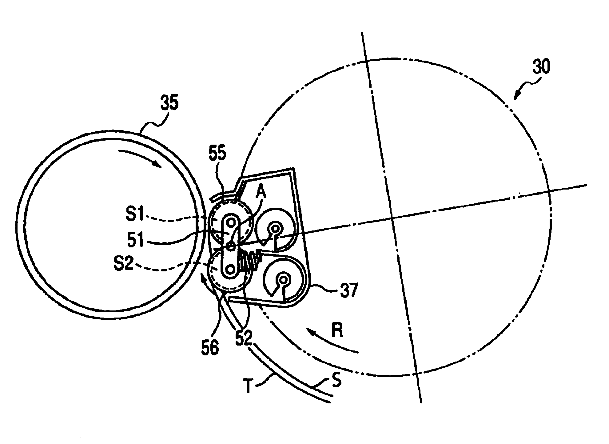
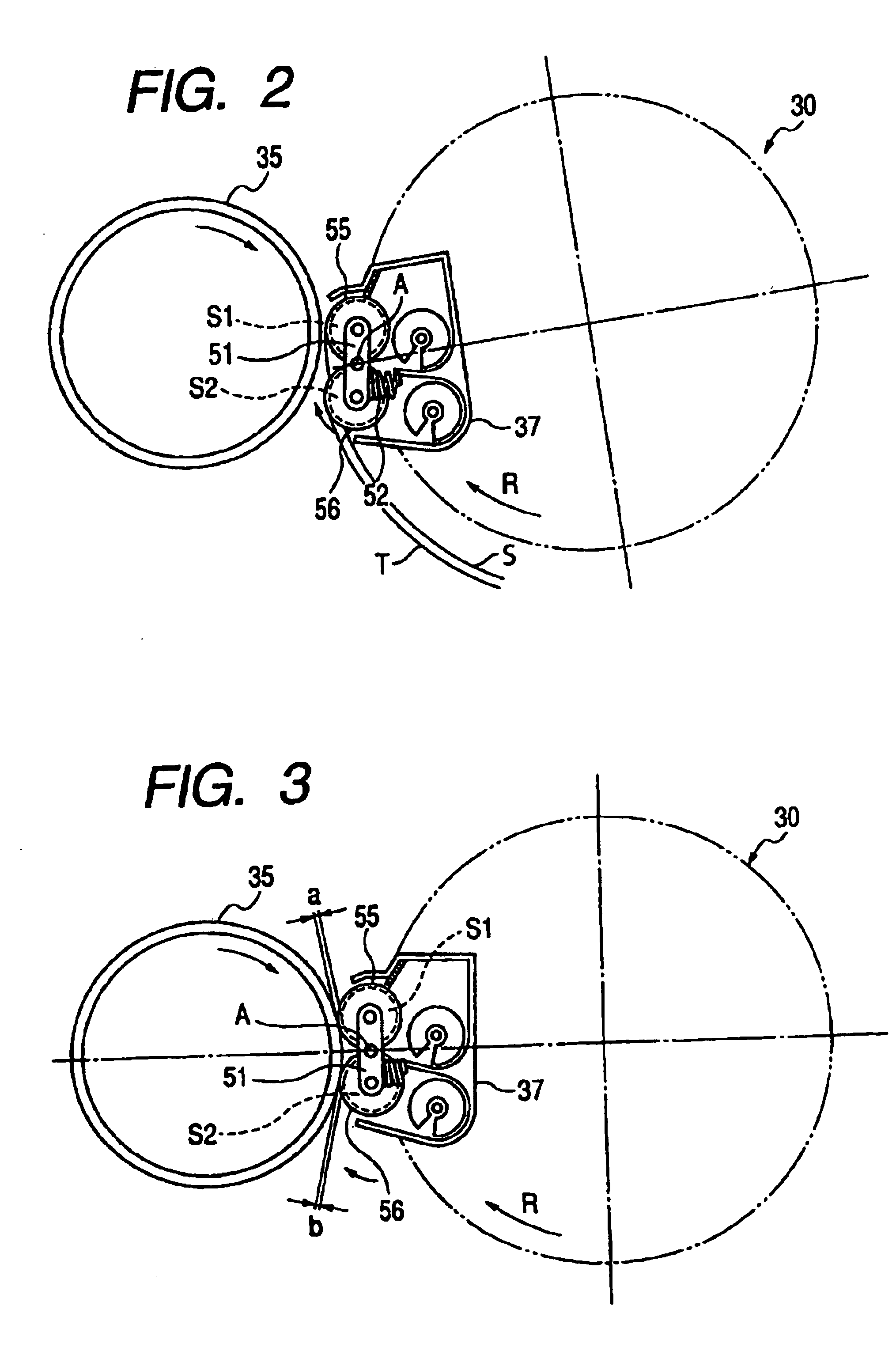
[0040]A positioning method for the developing sleeves in the present embodiment, as shown in FIG. 7, is to determine the positions of the developing sleeves S1 and S2 by utilizing the pivotally moving operation of the holding member caused by the regulating member 55 provided on the developing sleeve S1 on the upstream side with respect to the direction of rotation (the direction indicated by the arrow R in FIG. 7) of the rotary type developing apparatus 37 being hit against the photosensitive drum 35.

[0041]In FIG. 7, the developing sleeve S2 on the downstream side indicated by solid line is connected to the developing sleeve S1 by a holding member 51 counter-clockwisely pressed about a fulcrum A by a pressure spring 54, and this developing sleeve S2 is designed not to be hit against the photosensitive drum 35. The regulating member 55 of the developing sleeve S1 mov...


PUM


Abstract

An image forming apparatus has a plurality of developing devices for developing an electrostatic image formed on an image bearing member, a rotary member holding the plurality of developing devices and rotated in a route including a developing position, the rotary member selectively positioning any one of the developing devices at the developing position, each of the plurality of developing devices having a first developer carrying member and a second developer carrying member for carrying a developer thereon and carrying it to the image bearing member, and a holding member holding the first developer carrying member and the second developer carrying member and pivotally movably provided.

Description

BACKGROUND OF THE INVENTION[0001]1. Field of the Invention[0002]The invention relates to an image forming apparatus adopting an electrophotographic process or an electrostatic recording process, and particularly to an image forming apparatus such as a copying machine, a printer or a facsimile apparatus. More particularly, it relates to an image forming apparatus such as a copying machine, a printer or a facsimile apparatus capable of forming a full-color image.[0003]2. Description of Related Art[0004]In an image forming portion in an image forming apparatus such as a copying machine, a photosensitive member which is an image bearing member is charged by a charging apparatus, and is exposed to the image of an original at an exposure position by an exposing optical system to thereby form an electrostatic latent image on the peripheral surface of the photosensitive member, and this electrostatic latent image is developed by a developing apparatus to thereby form a developer image (tone...

Claims


Application Information

Patent Timeline
IPC IPC(8): G03G15/01G03G15/08
CPCG03G15/0121G03G15/0173G03G2215/0177
Inventor IKEDA, TAROSEKINE, HIROYUKI
Owner CANON KK
Why Eureka
Try Eureka