
Stool flushing device

a technology for flushing devices and toilets, which is applied in water installations, instruments, constructions, etc., can solve problems such as difficult assembly, large waste, and difficult to clean up

Inactive Publication Date: 2005-09-27
TOTO LTD
View PDF12 Cites 9 Cited by
  • Summary
  • Abstract
  • Description
  • Claims
  • Application Information

AI Technical Summary

Benefits of technology

The system accurately measures urine flow and adjusts cleaning water supply accordingly, conserving water and simplifying maintenance by eliminating the need for complex pressure sensors and ensuring efficient cleaning.

Problems solved by technology

However, in such automatic cleaning systems based on human detection, the toilet stool is flushed with a fixed quantity of cleaning water regardless of whether the toilet stool has been used or the quantity of urine, leading to a great deal of waste.
However, this cleaning system using a pressure sensor is constituted such that the trap portion and pressure sensor are connected by piping in order to detect the water pressure inside the trap, and hence water tightness must be secured in the piping connection portion at the trap portion over a long period of time.
However, in reality this is not easy.
Moreover, a protective member is required for preventing the infiltration of liquid or harmful gas into the sensor portion, making assembly difficult.
To prevent the water pressure-detecting piping portion from blocking, a portion of the cleaning water is supplied to clean the piping, but this leads to an even more complex constitution, making assembly difficult and becoming a possible cause of breakdowns.
Moreover, when a breakdown occurs in the piping portion, repairs from the back portion of the toilet stool can proceed only when the toilet stool is separated from the water supply pipe and drain pipe and moved away from the wall surface, and hence this system is highly unrealistic.
The basic issue in detecting the water pressure at the trap portion is the influence on pressure variation in the drain pipe.
Hence in reality, it is difficult to detect only urine reliably.

Method used


Image

  • Stool flushing device
  • Stool flushing device
  • Stool flushing device

Examples


Embodiment Construction

[0117]Embodiments of the present invention will be described below on the basis of the drawings.

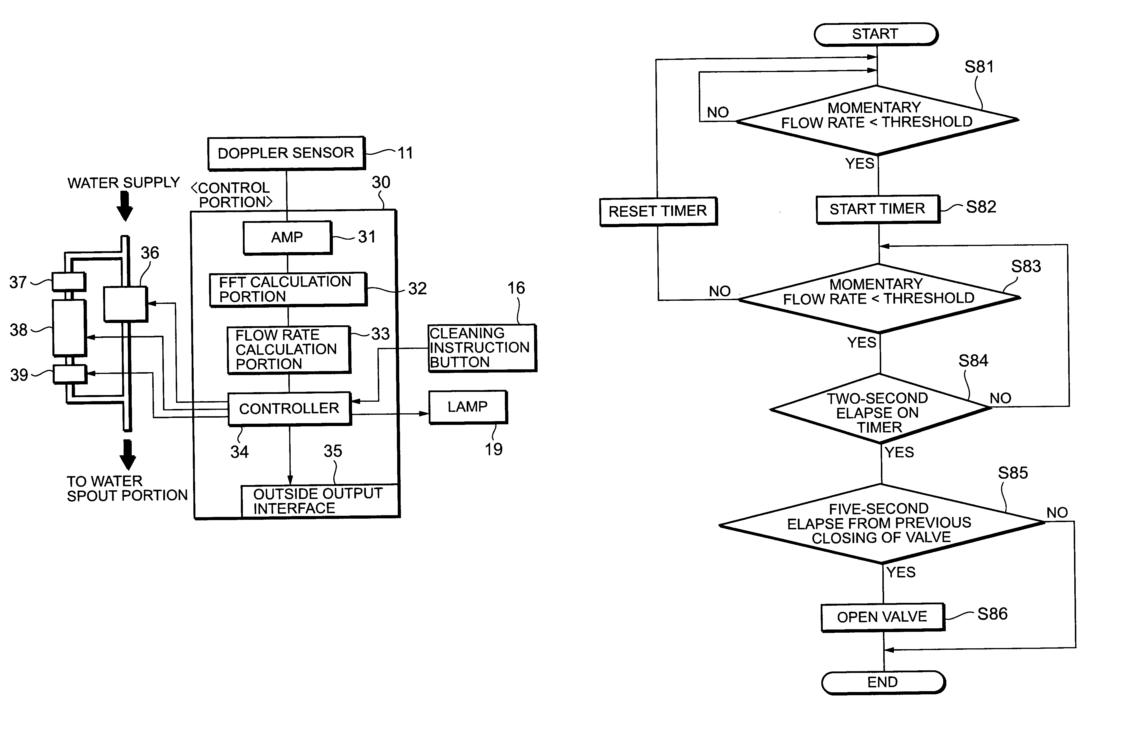
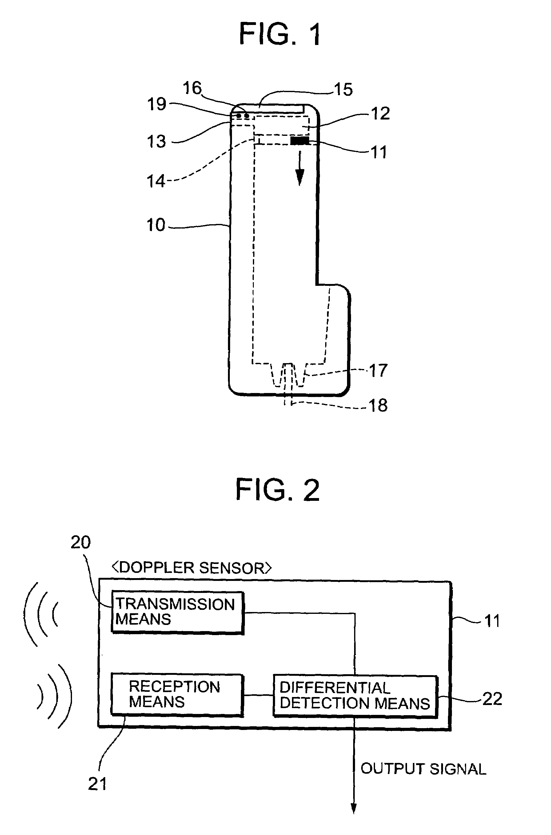
[0118]FIG. 1 is a view showing the constitution of a toilet stool to which the toilet cleaning device of the present invention is applied. A Doppler sensor 11 and a function portion 12 are installed in the interior of a toilet stool 10. The upper end of the toilet stool 10 is a lid 15, and hence maintenance work on the space which accomodates the Doppler sensor 11 and function portion 12 can be performed easily. A water supply portion 13 is provided in the upper back face of the toilet stool 10 for supplying water to clean the space inside a bowl portion of the toilet stool 10. Cleaning water spout 14 is provided in the upper portion of the bowl portion interior space. A cleaning instruction button 16 for discharging the cleaning water to the bowl portion interior space at the discretion of a sanitation worker, and a lamp 19 for notifying the condition of the toilet cleaning device are in...


PUM


Abstract

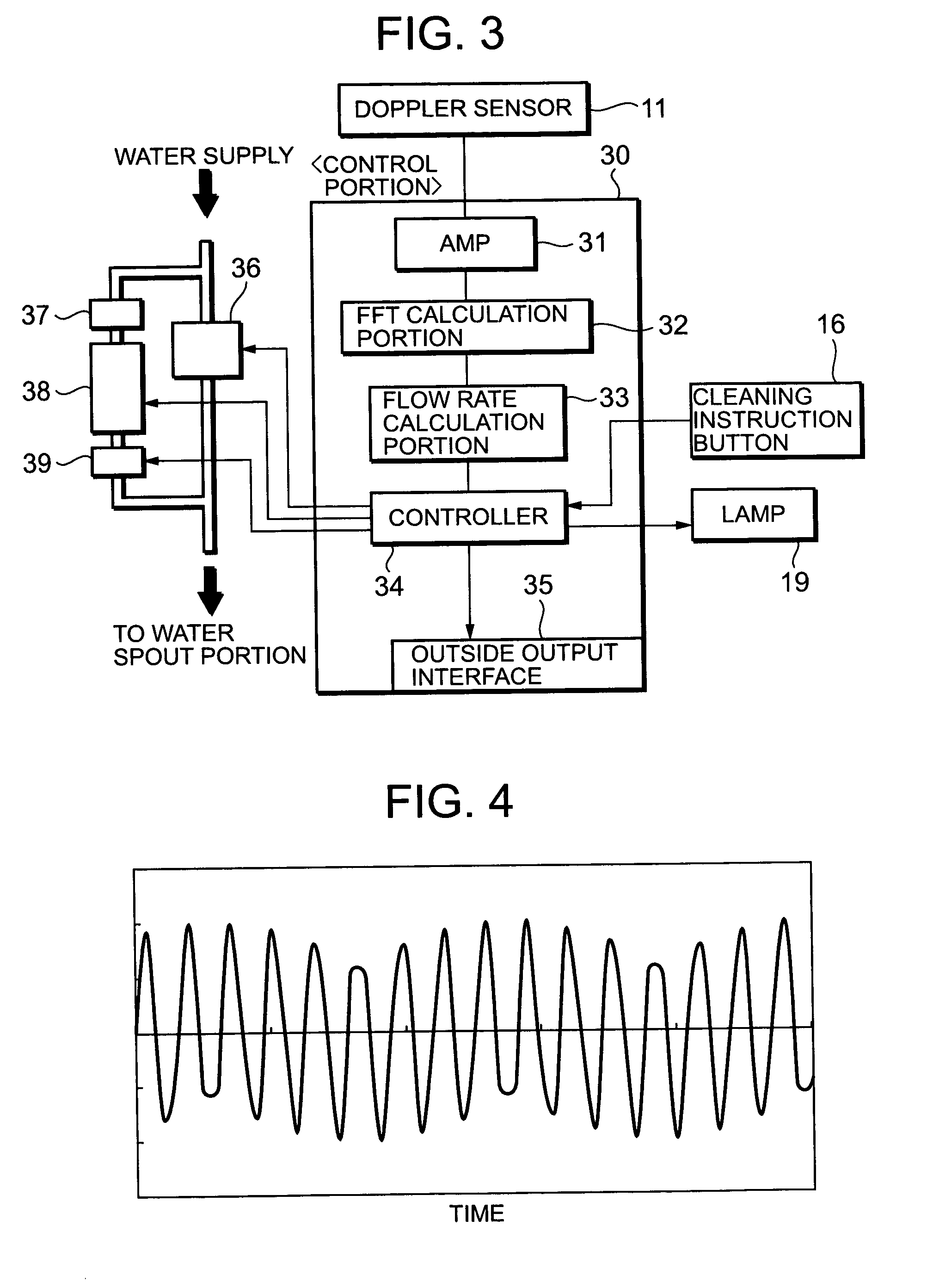
An object of the present invention is to provide a toilet cleaning device which is capable of cleaning a toilet stool by supplying cleaning water in an appropriate quantity corresponding to the state of usage by a user, which is provided with a self-diagnosis function for diagnosing cleaning water stoppage or the like, and which has a simple constitution so that maintenance can be performed easily. The output of a Doppler sensor 11 is amplified by an amp 31, and a frequency spectrum is determined by an FFT calculation portion 32. A flow rate is determined by conversion in a flow rate calculation portion 33 on the basis of the frequency spectrum. A controller 34 operates other devices on the basis of the flow rate calculated by the flow rate calculation portion 33 and the operational state of a cleaning instruction button 16. Cleaning water supply valve 36 is opened and closed in accordance with instructions from the controller 34. Electrolyzed water is generated in an electrolyzed water generating portion 38 to prevent the formation of urinary calculus in a drainpipe, and this electrolyzed water is discharged from a water spout when an electrolyzed water supply valve 39 is opened.

Description

TECHNICAL FIELD[0001]The present invention relates to a toilet cleaning device for cleaning a toilet stool, a water closet, and so on.BACKGROUND ART[0002]Conventionally, in order to automate the cleaning of the main body of a toilet following usage, a human detection sensor such as an infrared sensor is installed in the toilet stool, and if the human detection sensor detects a user for a fixed period of time or more, the sensor then detects the departure of the user and flushes the toilet stool with a fixed quantity of cleaning water. However, in such automatic cleaning systems based on human detection, the toilet stool is flushed with a fixed quantity of cleaning water regardless of whether the toilet stool has been used or the quantity of urine, leading to a great deal of waste.[0003]A device for solving this problem, proposed in Japanese Patent Unexamined Publication No. H10-37284, detects variation in the water pressure at the trap portion of a toilet stool using a pressure sens...

Claims


Application Information

Patent Timeline
Patent Type & Authority Patents(United States)
IPC IPC(8): E03D13/00E03D3/00E03D5/00E03D5/10G01S13/00G01S13/56G01S13/88
CPCE03D3/00E03D5/105E03D13/00G01S13/56G01S13/88
Inventor TODOROKI, KENTAROSHINOHARA, KUNIAKIKOGURO, TOSHIOFURUTA, YUICHIIKUSHIMA, MIE
Owner TOTO LTD
Learn More