Modular heat recovery ventilation system

a ventilation system and module technology, applied in ventilation systems, lighting and heating apparatus, heating types, etc., can solve the problems of difficult and time-consuming replacement of filters employed in association with a conventional heat exchanger arrangement, the limited location of heat exchangers, and the inability to service fan related and other components. , to achieve the effect of low cost and ease of use and maintenan

Inactive Publication Date: 2005-09-27
BEUTLER CORP
View PDF17 Cites 16 Cited by
  • Summary
  • Abstract
  • Description
  • Claims
  • Application Information

AI Technical Summary

Benefits of technology

[0004]The system disclosed and claimed herein is characterized by its relative simplicity, relatively low cost and ease of use and maintenance. Utilizing the principles of the present invention, an individual can access and change filters associated with the apparatus from inside the living quarters of a home, despite the fact that the apparatus itself may be positioned in the attic. Furthermore, there is also ease of access to the interior of the enclosure of the apparatus so that a unitary blower assembly disposed therein can be removed from inside the enclosure for repair, servicing or replacement.

Problems solved by technology

Because heat exchangers require draining of condensate produced thereby, there are limitations and restrictions as to where heat exchangers can be located.
A location where a heat exchanger can be installed does not always lend itself to servicing of the fan related and other components associated with the heat exchanger.
Furthermore, replacement of filters employed in association with a conventional heat exchanger arrangement can be a difficult and time consuming task.

Method used


Image

  • Modular heat recovery ventilation system
  • Modular heat recovery ventilation system
  • Modular heat recovery ventilation system

Examples


Embodiment Construction

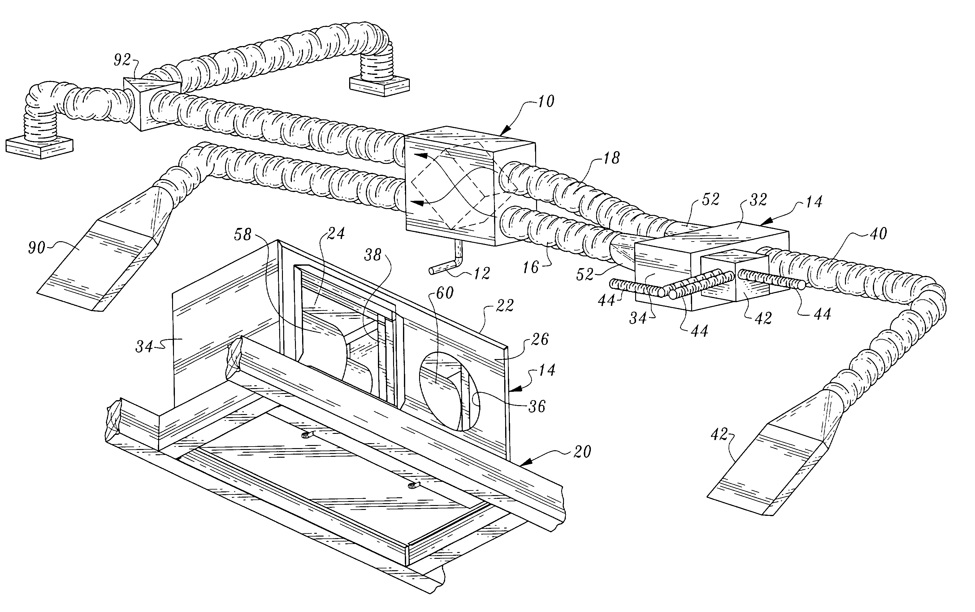
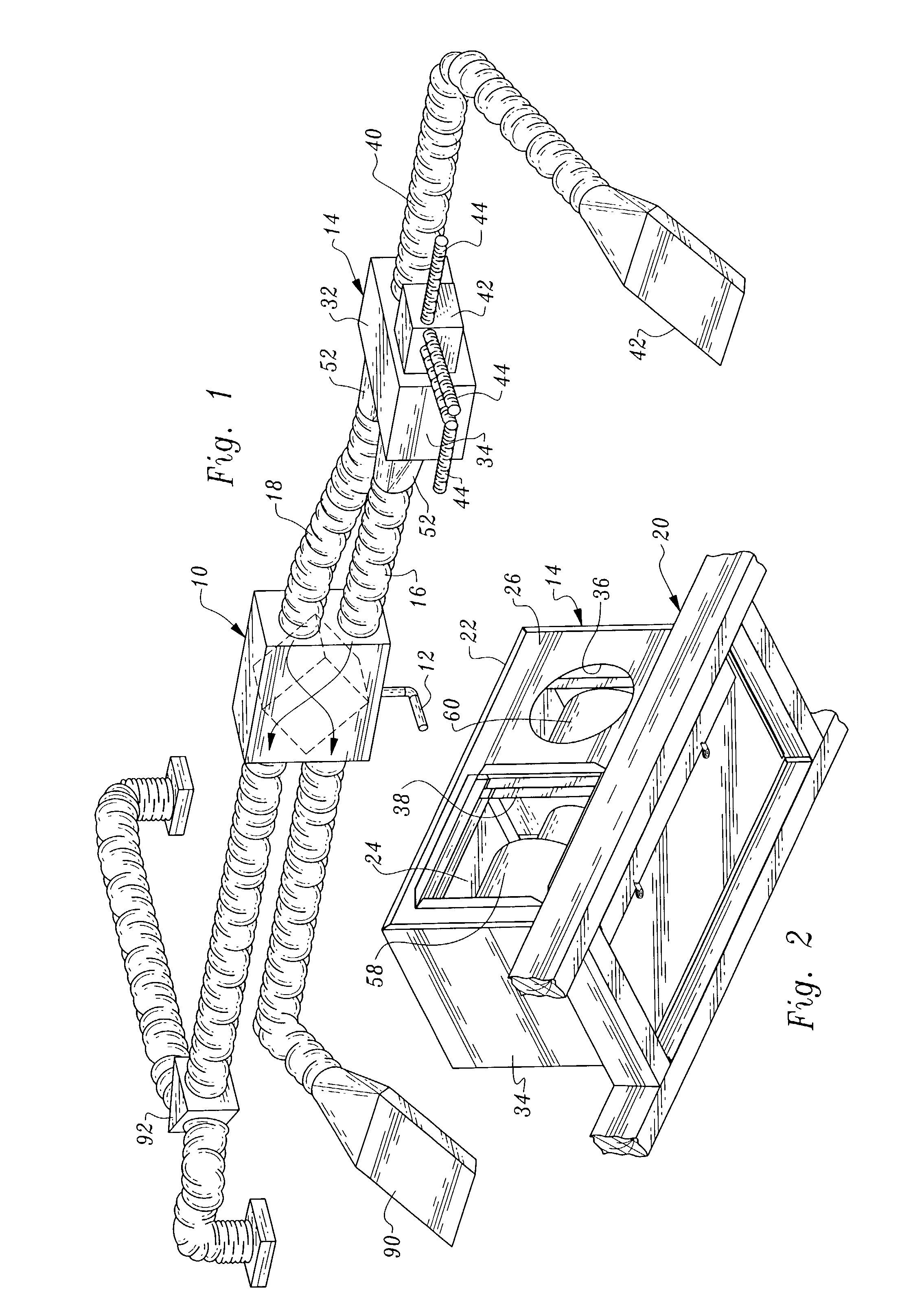
[0021]FIG. 1 illustrates a modular heat recovery ventilation system constructed in accordance with the teachings of the present invention. The system includes a heat exchanger 10 of any known suitable construction. A condensate drain 12 is associated with the heat exchanger. Operatively associated with the heat exchanger 10 and spaced therefrom is apparatus 14 which is in the general nature of a fan box. Ducts or conduits 16, 18 interconnect the apparatus 14 to the heat exchanger 10, these two appliances being spaced from one another and of modular construction. Thus, the positioning of the heat exchanger 10 in a house or other building does not dictate the location of apparatus 14 or vice versa.

[0022]FIG. 2 shows apparatus 14 mounted on framing of a house and more particularly on a bottom chord of a ceiling truss 20 located between an attic and the living space of a home. The apparatus 14 may be secured in position by any known expedient such as nails or threaded fasteners. As will...


PUM


Abstract

A modular heat recovery ventilation system includes a modular heat exchanger and a modular apparatus spaced from the heat exchanger for delivering both fresh air and exhaust air to the heat exchanger. The apparatus includes separate blowers for generating two separate air streams. The apparatus includes an access plate at the bottom thereof allowing access to the interior of the enclosure of the apparatus through a ceiling.

Description

TECHNICAL FIELD[0001]This invention relates to a system utilized to supply fresh air to the interior of a house or other building while at the same time exhausting stale air from the building. The exhaust air travels to a heat exchanger to either preheat or pre-cool the incoming supply air.BACKGROUND OF THE INVENTION[0002]The use of heat exchangers in residences and other buildings is well known. Typically heat exchangers employed in houses and other buildings incorporate a fan which causes air to flow through the exchanger. Because heat exchangers require draining of condensate produced thereby, there are limitations and restrictions as to where heat exchangers can be located. A location where a heat exchanger can be installed does not always lend itself to servicing of the fan related and other components associated with the heat exchanger. Furthermore, replacement of filters employed in association with a conventional heat exchanger arrangement can be a difficult and time consumi...

Claims


Application Information

Patent Timeline
Patent Type & Authority Patents(United States)
IPC IPC(8): F24F7/06F24F7/007F24F12/00
CPCF24F12/006Y02B30/563F24F2003/1635F24F2003/1614F24F8/108F24F8/194Y02B30/56Y02A50/20
Inventor DAY, MICHAEL SEANWYLIE, CALVIN RICHARDVENZKE, TRISTAN ADAIR
Owner BEUTLER CORP
Why Eureka
Try Eureka