Dimming ballast control IC with flash suppression circuit

a technology of dimming ballast and suppression circuit, which is applied in the direction of process control, instruments, light sources, etc., can solve the problems of lamp extinguishing, and achieve the effect of preventing lamp extinguishing, preventing lamp flashing, and preventing lamp extinguishing during rapid changes in dimming levels

Active Publication Date: 2005-09-27
INFINEON TECH AMERICAS CORP
View PDF7 Cites 27 Cited by
  • Summary
  • Abstract
  • Description
  • Claims
  • Application Information

AI Technical Summary

Benefits of technology

[0007]In accordance with the present invention, lamp flash is prevented by reducing the transition time from maximum brightness to the final low dimming level. The reduction in transition time gives the lamp the appearance of starting cleanly and smoothly, directly at the desired dimming level. The present invention provides an electronic ballast control for a fluorescent lamp that detects ignition of the lamp. The control method detects ignition at the earliest available time and closes the loop so that the system can transition to the minimum dimming setting before the human eye can detect a flash. The circuit measures the peak output current against an upper threshold as the current increases during the ignition ramp. When the peak current exceeds the upper threshold, the threshold is then decreased to a lower threshold. When the lamp ignites, the current decreases below the lower threshold and the circuit closes the dimming loop. The current supplied through the electronic ballast drops to the reduced power level threshold, the dimming control is active with a closed loop control.
[0008]Also, the lamp can extinguish during rapid changes in dimming levels. The present invention provides an electronic ballast control with a rate attenuation control for dimming changes to prevent lamp from extinguishing.

Problems solved by technology

Also, the lamp can extinguish during rapid changes in dimming levels.

Method used


Image

  • Dimming ballast control IC with flash suppression circuit
  • Dimming ballast control IC with flash suppression circuit
  • Dimming ballast control IC with flash suppression circuit

Examples


Embodiment Construction

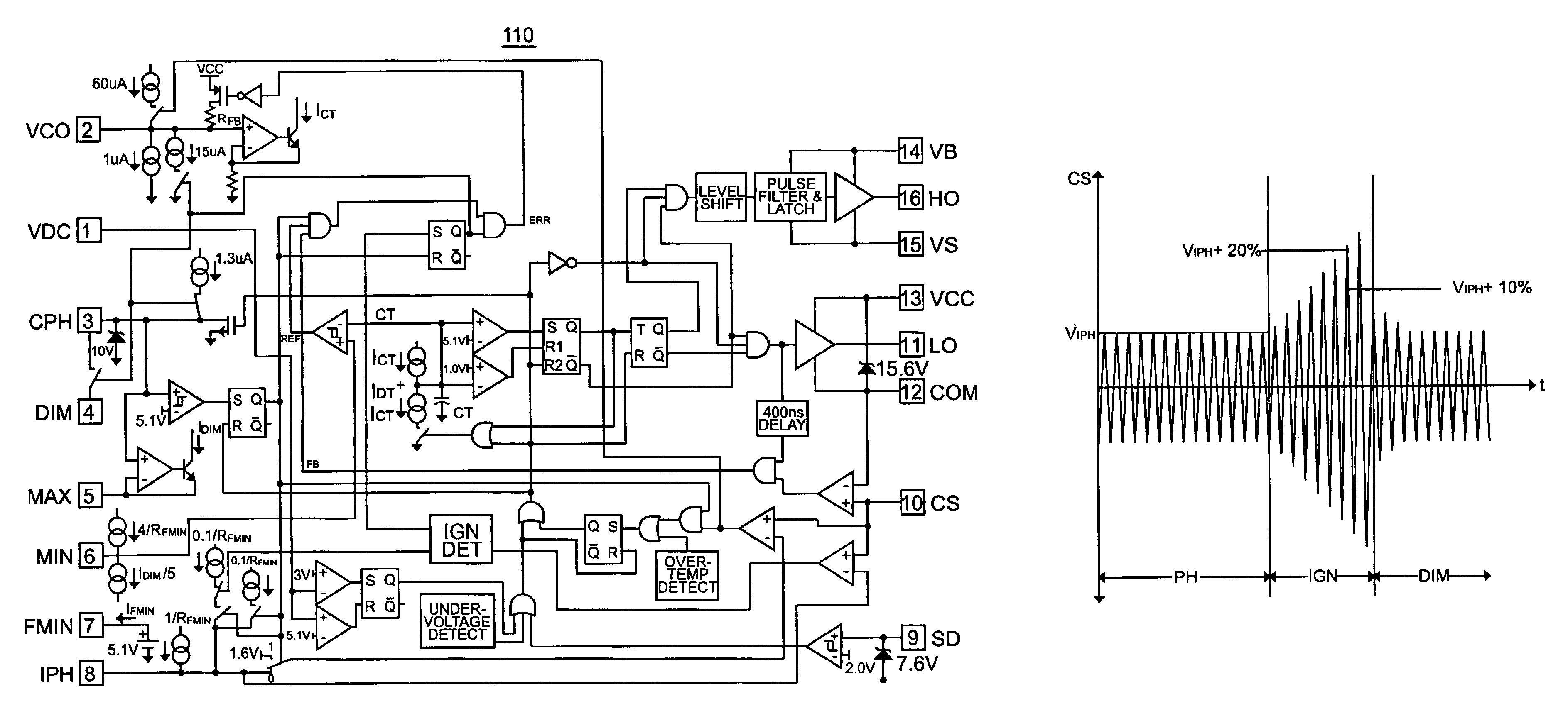
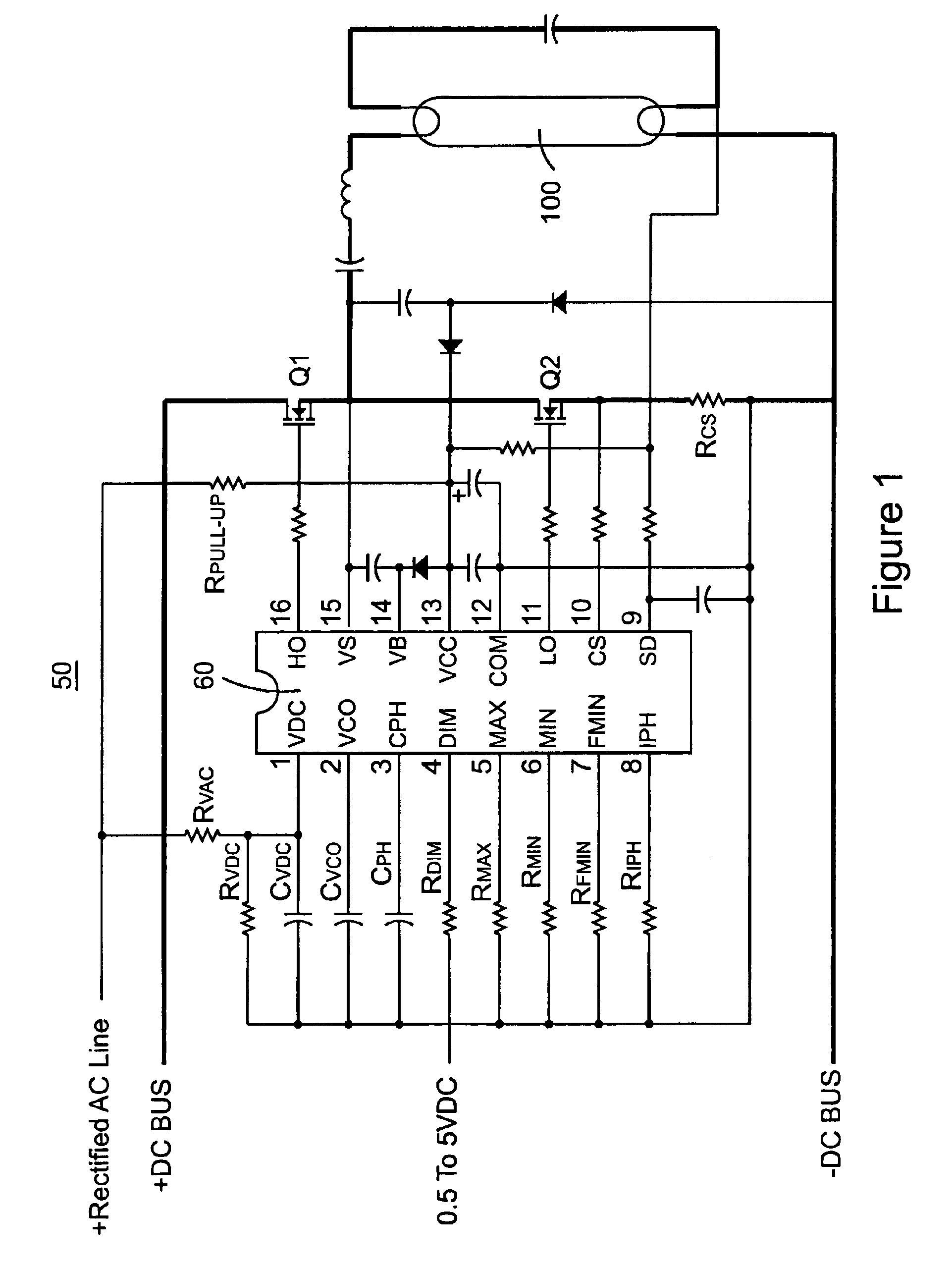
[0030]The present invention provides an improvement to a dimming electronic ballast controlled to prevent lamp flash. Referring now to FIG. 1, a typical circuit arrangement for an electronic ballast is illustrated as circuit 50. A fluorescent lamp 100 is operated by the electronic ballast based on input settings and parameter selection. The electronic ballast operates with a half bridge composed of two switches including a high side switch Q1 and a low side switch Q2. Switches Q1 and Q2 are operated by electronic ballast control IC 60 in accordance with the input command and parameter settings provided by external components on control IC 60. Control IC 60 provides a ballast control and a half bridge driver in a single IC, and is capable of sensing lamp power without the use of a current transformer. Control IC 60 provides closed loop lamp power control and preheat current control, the preheat time and current being programmable by external components. A lamp ignition detection feat...


PUM


Abstract

A dimming electronic ballast control provides flash suppression by igniting the fluorescent lamp at a high power level, and then reducing the power output level to the appropriate dimming set level. The electronic ballast includes an integrated circuit that uses closed loop phase control and a VCO to control a switching frequency of a half bridge, which in turn controls power delivered to the fluorescent lamp. Current through the half bridge is sensed to provide closed loop control. The current sense signal is used to provide a high power level in the electronic ballast during ignition of the lamp, and as a phase detector for the phase control. A rate of change control circuit controls the speed of adjustment between power level settings, especially during ignition of the lamp. The electronic ballast provides a wide linear dimming range with fault detection and flash suppression.

Description

RELATED APPLICATION[0001]The present application is based on and claims benefit of U.S. Provisional Application No. 60 / 440,926, filed Jan. 16, 2003, entitled Dimming Ballast Control IC with Flash Suppression Circuit, to which a claim of priority is hereby made, and which is incorporated in its entirety herein by reference.BACKGROUND OF THE INVENTION[0002]1. Field of the Invention[0003]The present invention relates generally to electronic ballasts for fluorescent lamps, and relates more particularly to electronic ballast controls that can prevent fluorescent light flashes.[0004]2. Description of the Prior Art[0005]Electronic ballasts for fluorescent lamps are well known, particularly those that operate with a switching half bridge. Such an electronic ballast is illustrated in U.S. Pat. No. 6,008,593 to International Rectifier Corporation. Electronic ballast controls have evolved to include dimming functions, and in particular substantially linear dimming control. One type of dimming ...

Claims


Application Information

Patent Timeline
Patent Type & Authority Patents(United States)
IPC IPC(8): G05F1/00H05B41/392
CPCH05B41/3921Y10S315/07Y10S315/04
Inventor RIBARICH, THOMAS
Owner INFINEON TECH AMERICAS CORP
Why Eureka
Try Eureka