
Wide input voltage range light emitting diode driver

a light-emitting diode and input voltage range technology, applied in the field of communication circuits, can solve the problems of limiting the utility of a given driver circuit, not allowing the same led driver circuit to be used, and not allowing either ac or dc voltage, so as to reduce the current flow through the collector-emitter path, reduce the base bias, and reduce the current flow

Active Publication Date: 2005-09-27
ADTRAN
View PDF2 Cites 22 Cited by
  • Summary
  • Abstract
  • Description
  • Claims
  • Application Information

AI Technical Summary

Benefits of technology

The present invention provides a current-regulating driver circuit for LEDs that can maintain a constant level of illumination over a wide range of input voltage. The circuit uses a pair of input / output nodes to connect to a voltage source, which can be either an AC or a DC source. A limiting resistor and a current sense transistor are used to regulate the current flow through the LED, ensuring that the LED current is always larger than the base bias current of the LED current supply transistor. This circuit design allows for a wide range of input voltage and ensures a constant level of illumination from the LED.

Problems solved by technology

This limits the utility of a given driver circuit; moreover, the voltage must be a DC voltage of the proper polarity.
It does not allow the same LED driver circuit to be used in the presence of a widely varying input voltage, nor does it allow for either AC or DC voltage.

Method used


Image

  • Wide input voltage range light emitting diode driver
  • Wide input voltage range light emitting diode driver

Examples


Embodiment Construction

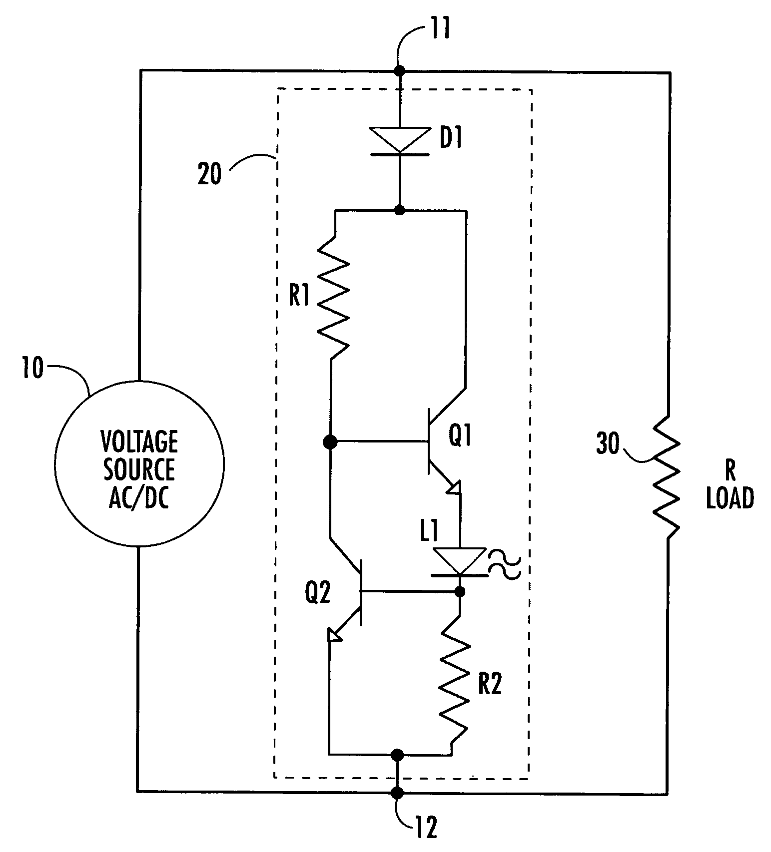
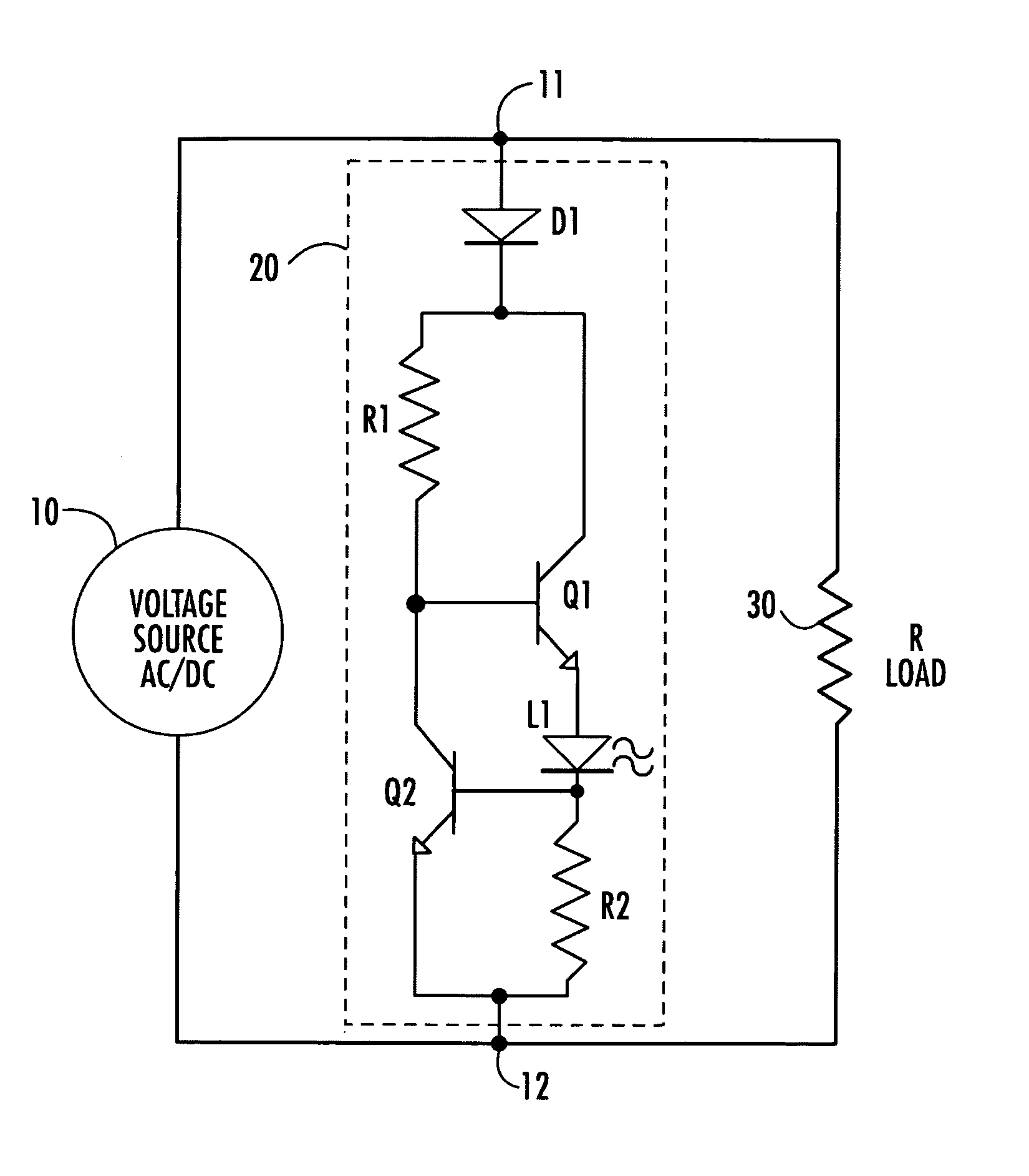
[0008]The overall architecture of the light-emitting diode (LED) circuit in accordance with the present invention is shown diagrammatically in the single FIGURE of drawings, as comprising respective first and second nodes 11 and 12 through which a voltage source 10, which may comprise either an AC or a DC voltage source, is coupled to a load, shown as a resistive load 30 for purposes of simplification. The LED circuit of the invention is contained in broken lines 20 and comprises an input rectifying diode D1 having its anode coupled to node 11 and its cathode coupled to each of a first end of first, series limiting resistor R1 and to the collector of a first bipolar (NPN), LED current supply transistor Q1. Input diode D1 has a peak inverse breakdown voltage that is higher than the peak operating voltage supplied by source 10 to nodes 11 and 12. Input diode D1 serves to allow current to pass through the circuit in only one direction and allows the invention to be employed with an AC ...


PUM


Abstract

A current-regulating driver circuit for a light emitting diode (LED) maintains energization drive to and thereby illumination provided by the LED at a prescribed, substantially constant value, over a relatively wide range of input (AC or DC) voltage. First and second input nodes are coupled to a source of AC or DC voltage and to a load, powered by the source of AC or DC voltage. An input rectifying diode is coupled to the first input node. A controlled current flow element is coupled in a first current flow path between the input rectifying diode and the LED and is controllably operative to supply current for illuminating the LED. A controlled current regulation circuit that includes a sense resistor coupled in series with the LED is coupled with the controlled current flow element between the first and second nodes, and is operative to regulate current supplied over the first current flow path by the controlled current flow element to the LED, and thereby accommodate variations in the value of the source of AC or DC voltage.

Description

FIELD OF THE INVENTION[0001]The present invention relates in general to communication circuits and the like, and is particularly directed to a new and improved indicator circuit, specifically, a current-regulating driver circuit for a light emitting diode (LED), which is operative to maintain the energization drive to and thereby the illumination provided by the LED at a prescribed, substantially constant value, over a relatively wide range of input (AC or DC) voltage.BACKGROUND OF THE INVENTION[0002]Electronic circuits often employ light emitting diodes (LEDs) to indicate the presence of an operational voltage or electrical power. In a typical application, the LED will be coupled in parallel with the load that is consuming electrical power. In order to operate within specified parameters, LEDs require a relatively narrow range of direct current and voltage. As a result, to use an LED as an indicator, it is customary practice to employ a series, current-limiting resistor that sets t...

Claims


Application Information

Patent Timeline
Patent Type & Authority Patents(United States)
IPC IPC(8): H05B37/00H05B37/02
CPCH05B33/0809Y02B20/30H05B45/395H05B45/37
Inventor BERTRAND, JEFFREY JOHN
Owner ADTRAN
Features
  • Generate Ideas
  • Intellectual Property
  • Life Sciences
  • Materials
  • Tech Scout
  • Unparalleled Data Quality
  • Higher Quality Content
  • 60% Fewer Hallucinations
Learn More