
Image display unit

a display unit and image technology, applied in the field of image display devices, can solve the problems of poor visibility, small image contrast, difficult to double the brightness of the display on the image display means b>3/, and the viewer appears to be a small number, so as to achieve excellent visibility, increase cost and power consumption, and large contrast

Inactive Publication Date: 2005-09-27
MITSUBISHI ELECTRIC CORP
View PDF4 Cites 10 Cited by
  • Summary
  • Abstract
  • Description
  • Claims
  • Application Information

AI Technical Summary

Benefits of technology

[0028]The present invention aims at overcoming the above problem and has its object to obtain an image display device that is capable of displaying image having a large contrast and excellent visibility to the viewer even when there is the influence of external light and when the luminance in displaying black has a large value due to the characteristics of an image display means; and that is free from problems of increasing cost and power consumption and decreasing useful lifetime in the image display means, which are caused by reducing an increase in ratio to luminance when displaying white.

Problems solved by technology

That is, when there is the influence of external light, the viewer seems that the image has a small contrast and poor visibility.
There is also such technical background that it is very difficult to double the brightness of display on the image display means 3, due to problems of cost, problems of power consumption, and problems of useful life.
Thus, the conventional image display device suffers from the problem that when there is the influence of external light or when the luminance in displaying black has a large value due to the characteristics of the image display means, a ratio to white (Y / Ymax), which is a ratio of a luminance displayed for each image data to a luminance in displaying white, is considerably large and the viewer seems that the image has a small contrast and poor visibility.

Method used


Image

  • Image display unit
  • Image display unit
  • Image display unit

Examples


Embodiment Construction

[0098]1. First Preferred Embodiment

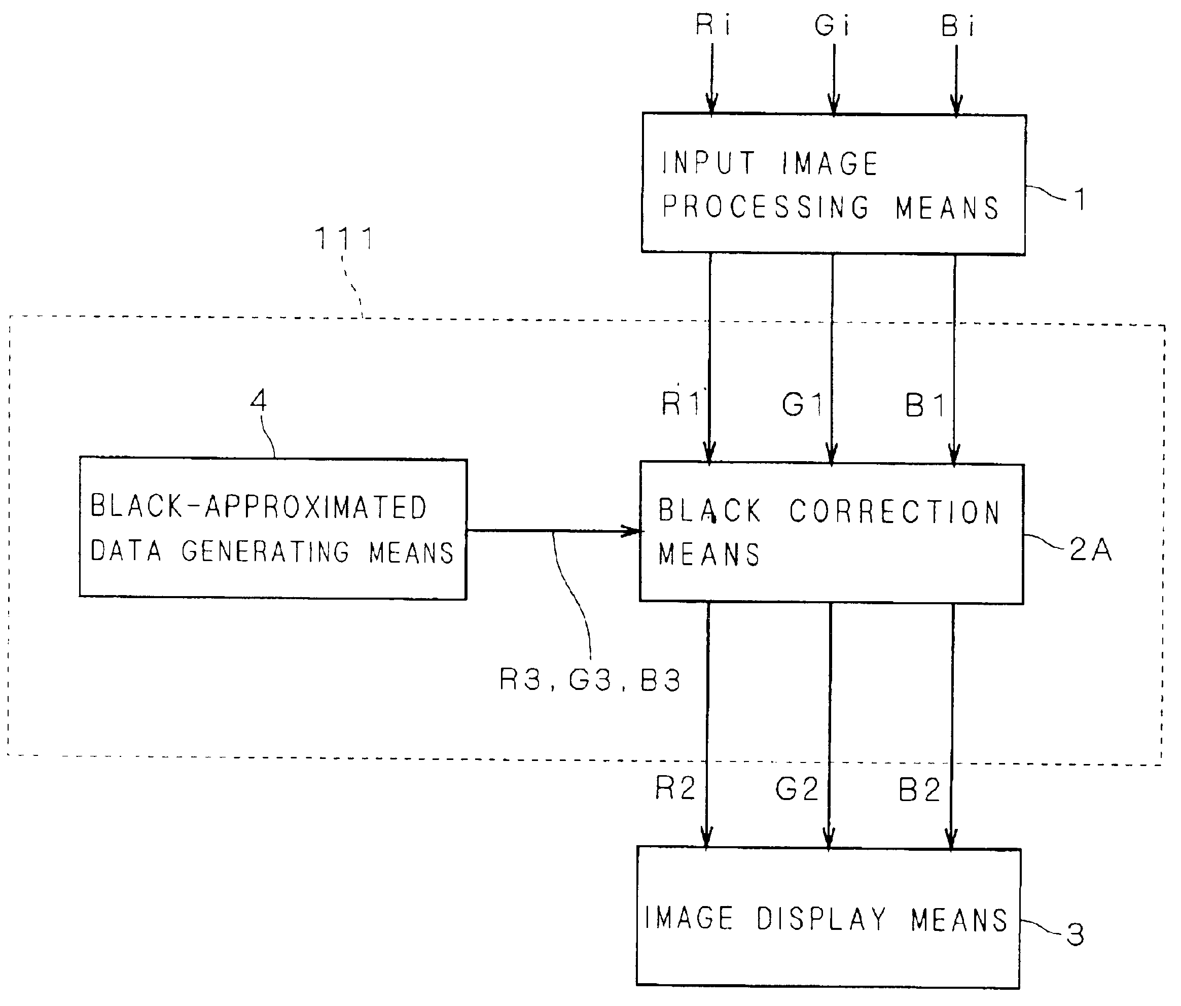
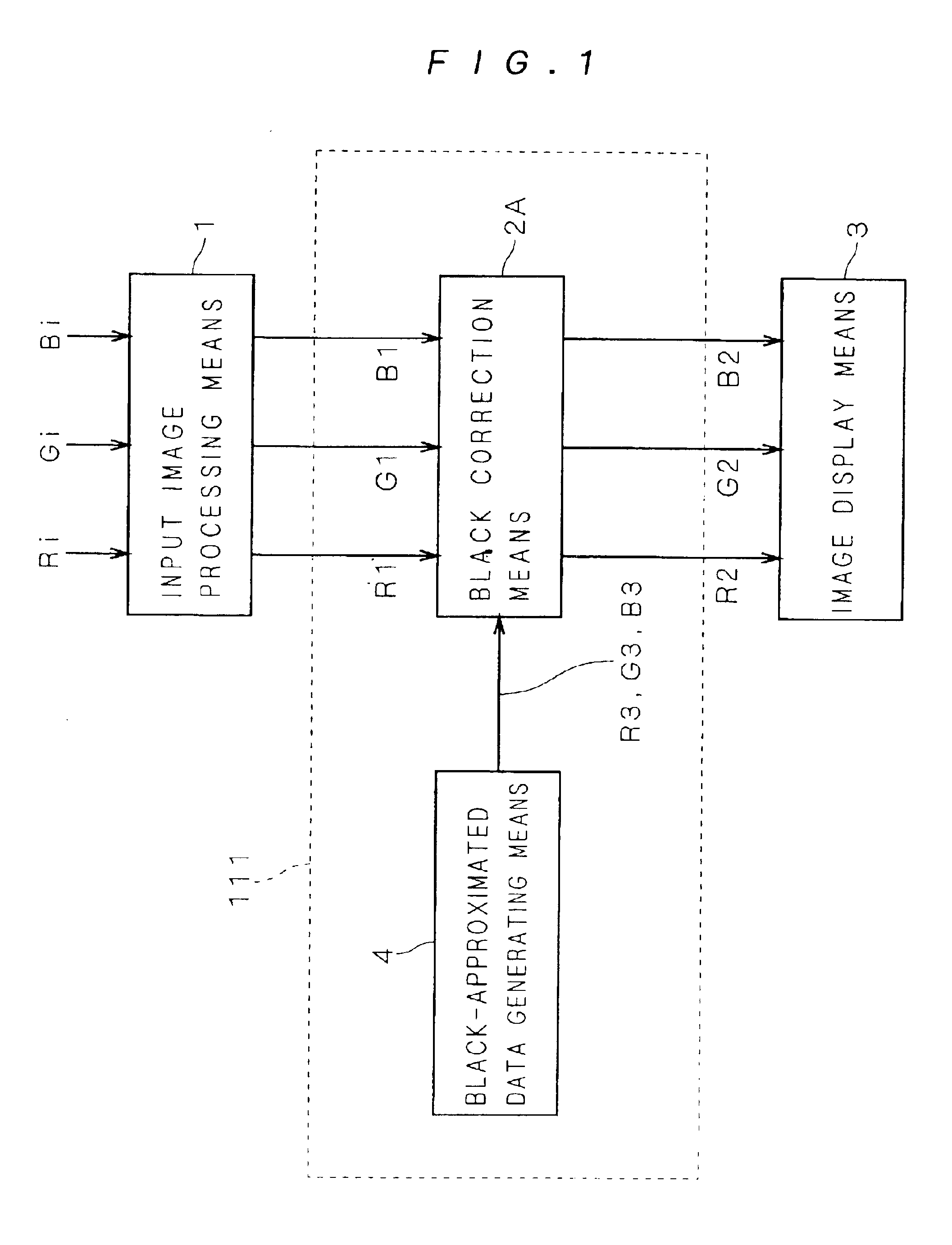
[0099]FIG. 1 is a block diagram showing the configuration of an image display device in a first preferred embodiment of the invention. As shown in FIG. 1, the image display device of the first preferred embodiment is configured with an input image processing means 1, black correction means 2A, image display means 3, and black-approximated data generating means 4. A black correction part 111 is made of the black correction means 2A and black-approximated data generating means 4.

[0100]The operation of the image display device of the first preferred embodiment will be described below by referring to FIG. 1. Image data Ri, Gi, and Bi that are composed of three color data inputted to the image display device are inputted to the input image processing means 1. The input image processing means 1 subjects the inputted image data Ri, Gi, and Bi to input image processing and outputs after-input-processing data R1, G1, and B1 composed of three color data.

[010...


PUM


Abstract

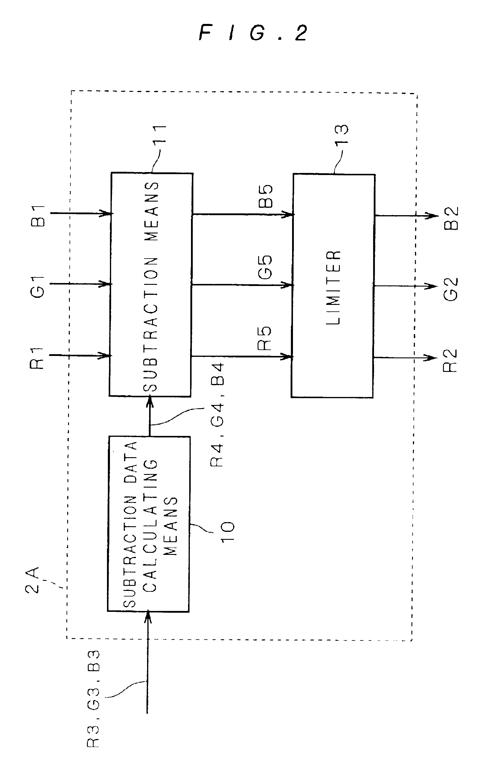
The invention relates to an image display device displaying color image and has its object to display image having a large contrast and excellent visibility to the viewer in an image display device particularly used under environment where external light exists.To achieve the above object, black-approximated data generating means 4 generates black-approximated data R3, G3, and B3 that are data related to chromaticity in displaying black on image display means 3. Black correction means 2A subtracts subtraction data R4, G4, and B4 that have the same value as the black-approximated data R3, G3, and B3, from after-input-processing image data R1, G1, and B1, thereby to calculate after-black-correction image data R2, G2, and B2. The image display means 3 emits in response to the values of the after-black-correction image data R2, G2, and B2, thereby to perform image display processing on a predetermined screen.

Description

[0001]This application is the national phase under 35 U.S.C. §371 of PCT International Application No. PCT / JP00 / 08755 which has an International filing date of Dec. 11, 2000, which designated the United States of America.TECHNICAL FIELD[0002]The present invention relates to an image display device displaying color image, such as monitors and projectors, and in particular, to an image display device used under environment where external light exists, as well as an image display device that has a large value of luminance when displaying black because of its characteristics.BACKGROUND ART[0003]FIG. 29 is a block diagram showing an example of configurations of conventional image display devices. The operation of a conventional image display device will be described below with reference to FIG. 29. This image display device is configured with an input image processing means 1 and an image display means 3, as shown in FIG. 29.[0004]Referring to FIG. 29, image data Ri, Gi, and Bi that are ...

Claims


Application Information

Patent Timeline
IPC IPC(8): G09G5/02G09G3/22
CPCG09G5/02G09G3/22G09G2310/0275
Inventor KAGAWA, SHUICHISUGIURA, HIROAKITAKAHASHI, MARIKOMATOBA, NARIHIROTERAMOTO, KOHEI
Owner MITSUBISHI ELECTRIC CORP
Learn More